Volkswagen Golf Service & Repair Manual: Adjusting door
| Special tools and workshop equipment
required |
| |
Door alignment tool -3320- |
| |
Universal joint for 3320 -3320/1- |
| |
Torque wrench -V.A.G 1331- |
|
|
|
| |
|
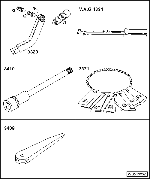
Removal wedge -3409- |
 Note
Note
| |
Only the adjustment for the left front door is described. The
adjustment of the right front door is similar. |
| |
Vehicle must be standing on its wheels when front door adjustment is
performed. |
| |
The rear door is correctly adjusted when all shut lines are even
when closed. it is not protruding too far inwards or outwards, and when
the contours are flush with each other. |
| |
For checking gaps/shut lines refer to
→ Rep. gr.00. |
| |
After installing or alignment, carry out corrosion protection
measures on hinges and screws/bolts. |
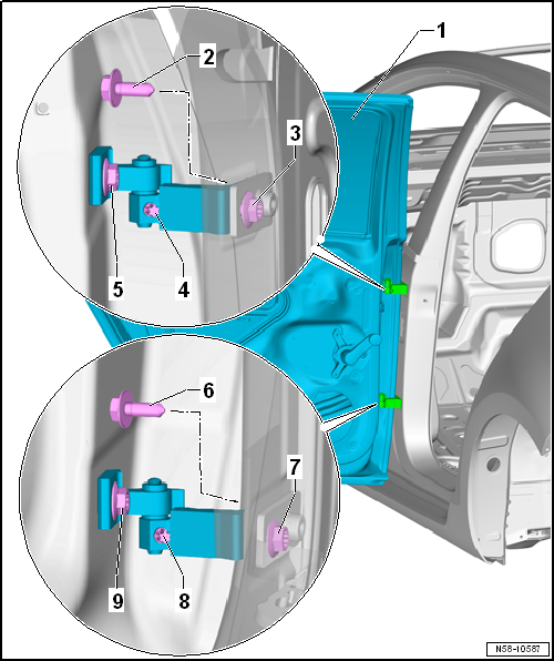
| To be able to adjust gaps correctly, bolts -2-,
-3-, -6- and
-7- on B-pillar must be loosened. |
| – |
The B-pillar lower trim must be removed for bolts
-3 and 7-. |
| Adjusting for flush fitting |
| In order to adjust flushness correctly, bolts
-5- and -9- must be loosened. |
| Use door alignment tool -3320- with appropriate bit for this. |
Note
| Other measures, such as raising the rear door, will prove pointless.
Subsequent pressure from above will cause the door to sack again at the
back. |
| – |
Adjusting striker pin
→ Chapter. |
| |
→ Chapter „Assembly overview - door“ |
Special tools and workshop equipment
required
Door alignment tool -3320-
Universal joint for 3320 -3 ...
Special tools and workshop equipment
required
Torque wrench -V.A.G 1331-
...
© 2016-2026 Copyright www.vwgolf.org


 Removing and installing door
 Adjusting striker pin