Volkswagen Golf Service & Repair Manual: Removing and installing door
| Special tools and workshop equipment
required |
| |
Door alignment tool -3320- |
| |
Universal joint for 3320 -3320/1- |
| |
Torque wrench -V.A.G 1331- |
|
|
|
 Note Note
| The removal and installation sequence is described for
the rear left door only. Removal and installation of the rear
right door are similar. |
|
|
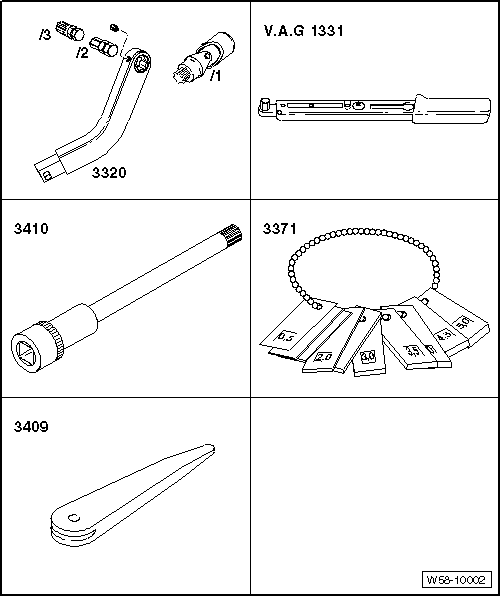
Removal wedge -3409- |
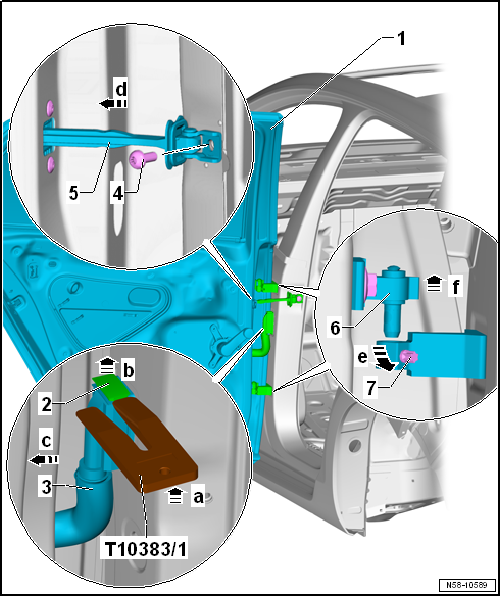
| – |
Press wedge -T10383/1- between bellows -3-
and locking mechanism -2--arrow a-. |
| – |
Push locking mechanism upwards -2- with
wedge -T10383/1--arrow b- and separate
electrical connector -3- from coupling
station -arrow c-. |
| – |
If fitted, remove covers of bolts -7-. |
| – |
Loosen bolts -7- at hinges
-arrow e-, but do not remove them. |
| – |
Unscrew bolt -4- for door retaining
strap -6-. |
| – |
Push door retaining strip -6- inwards
-arrow d-. |
| – |
Lift front door -1- with upper parts of
hinges -6- upwards
-arrow f- out of lower parts of hinges. |
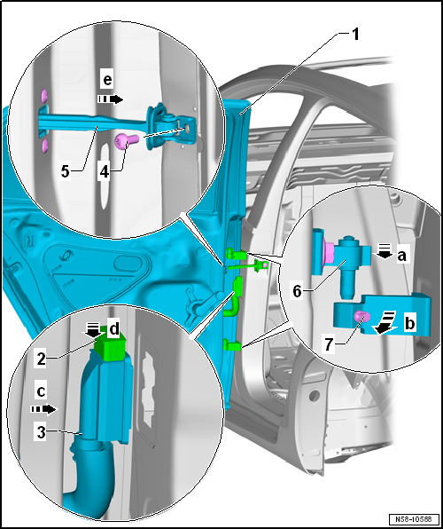
| Install in reverse order of removal. To this end, the following
should be observed: |
 Caution Caution
| Prior to installing the rear door, the door
retaining strap must be folded towards the inside of the vehicle
in order to avoid damage to the paintwork. |
|
Note
| After installation of the rear door, the hinge arms must be flush
one above the other. |
| – |
Adjust rear door -1-
→ Chapter. |
| – |
Observe front door shut lines -1-
→ Rep. gr.00. |
| |
→ Chapter „Assembly overview - door“ |
Note
Only the left side is shown. The right side is similar.
After renewal of B-pillar, the specified torque for bolts
-2 and 5- as well as for
...
Special tools and workshop equipment
required
Door alignment tool -3320-
Universal joint for 3320 -3 ...
Other materials:
Removing and installing wheel housing trim, saloon
Note
Removal and installation are described for the left
vehicle side. Follow same instructions for the right side as
appropriate.
Special tools and workshop equipment
required
...
Renewing LSU Lambda probe (6-pin)
Note
If necessary, replace attachment parts, cable ties or
marking rings to match the uniform probe to the defective probe
as specified.
The wires should not be crimped or cut as otherwise the
function of the L ...
Removing and installing centre armrest
Special tools and workshop equipment
required
Torque wrench -V.A.G 1410-
Removing
–
Open lid -2- for
through-loading ...
© 2016-2026 Copyright www.vwgolf.org

 Assembly overview - door
 Adjusting door