Volkswagen Golf Service & Repair Manual: Adjusting clutch engagement
| The position of the engagement bearings “K 1” and “K 2” must
only be adjusted after the following work: |
| Engaging levers were renewed. |
| Small ball pin for engaging lever “K 2” has been renewed. |
| Engagement bearings were renewed. |
 Note Note
| There is no need to adjust anything if all the named parts
have only been removed and reinstalled. |
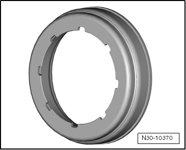
| The retaining ring must be renewed in each case. |
| Special tools and workshop equipment
required |
|
|
|
| Not shown: Depth gauge, digital 300 mm -VAS 6594- |
| Dual clutch removed
→ Chapter. |
| The gearbox flange must be level to assure good contact with
the ruler. |
| Mechatronic unit for dual clutch gearbox -J743- built into
gearbox. |
 Caution
| Risk of damage to clutch and other components! |
| Mounting for engaging lever and entire mechanism of
engagement bearing must be dry and free of oil or
grease. |
|
|
|
|
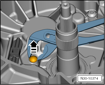
| Removing and installing ball pin |
| – |
Use pliers to remove ball-head pin. |
|
|
|
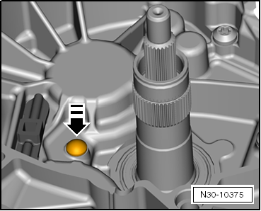
| – |
Push in »new« ball pin by hand,
if necessary using a plastic hammer and drift to tap it in. |
Note
| To avoid damage to ball pin, only tap the drift lightly with
the plastic head hammer. |
|
|
|
Note
| If dimension “B” has already been determined, it is now
possible to proceed with step “2” of the measurement
→ Anchor |
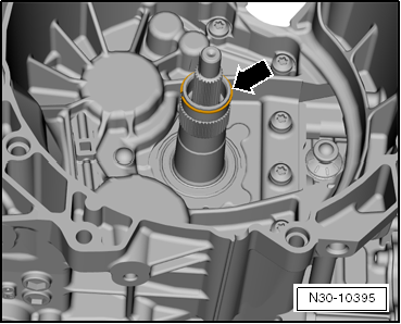
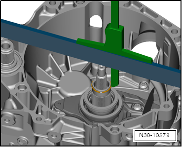
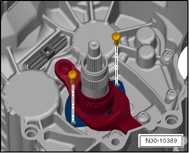
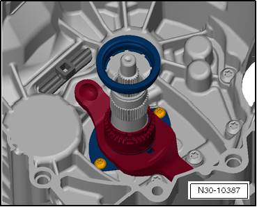
| – |
Install previously used retaining ring
-arrow- of outer input shaft. |
|
|
|
| 1st step: Determine dimension “B” for clutch “K 1” and “K 2” |
|
|
|
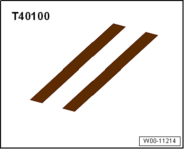
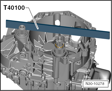
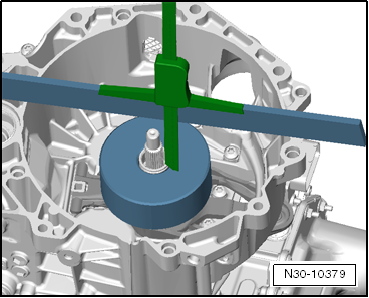
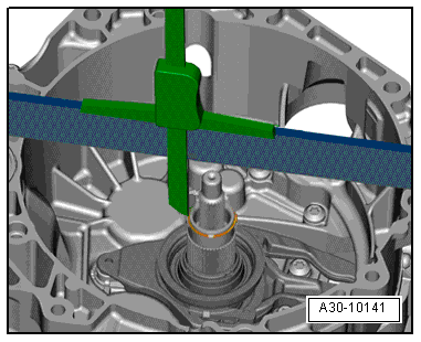
| – |
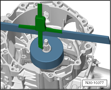
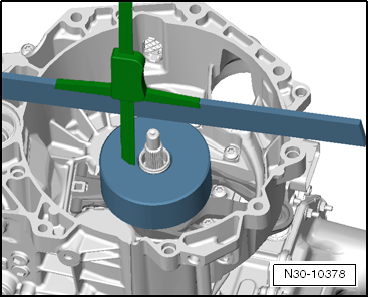
Place ruler -T40100- upwards across end of shaft onto
gearbox flange. |
Caution
| Risk of false measurements. |
| The ruler -T40100- should remain in this position
for the following measurements. Do not turn over, do not
remove. |
|
|
|
|
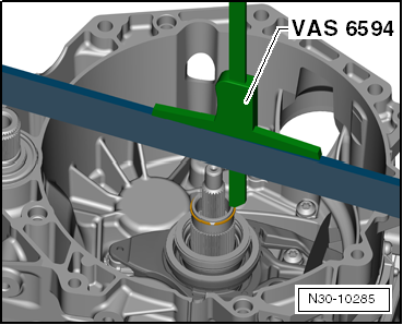
| – |
Fit digital 300 mm depth gauge -VAS 6594- on top of ruler
-T40100-. Position depth gauge rod on outer input shaft. |
| – |
Set depth gauge to “0”. |
|
|
|
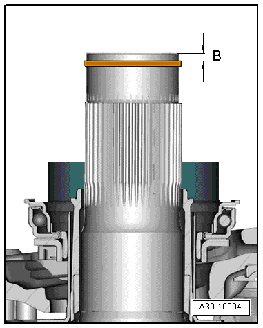
| – |
Position depth gauge rod on retaining ring, as show in
diagram. |
| – |
In this position, determine dimension “B1”
to retaining ring. |
| Example: dimension “B1” = 2.62
mm |
|
|
|
| – |
Remove retaining ring -arrow-
of outer input shaft and dispose. |
Note
| It is not permissible to reuse the retaining ring. |
|
|
|
| 2nd step: Determine dimension “A 1” for clutch engagement
bearing “K 1” |
|
|
|
| – |
Insert large engaging lever. |
Caution
| Risk of false measurements. |
|
| – |
Check that engaging lever is seated correctly. |
|
|

|
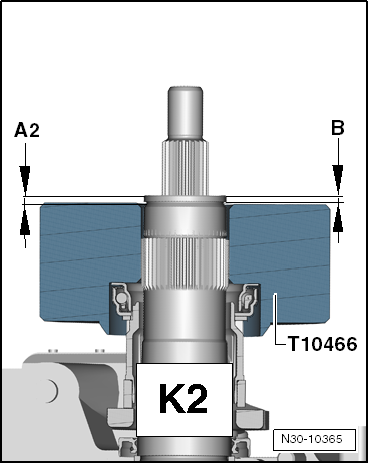
| – |
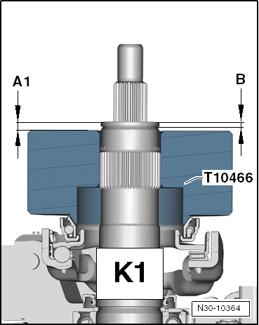
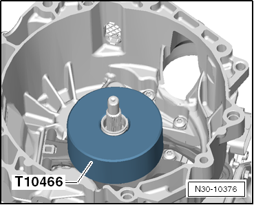
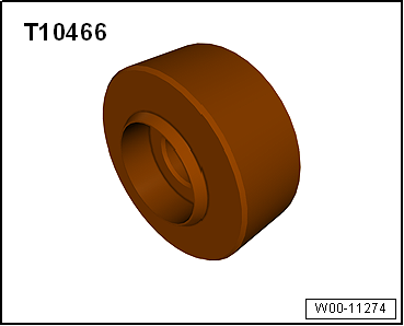
Place end gauge -T10466- on large engagement bearing. Flat
side faces upwards. |
| – |
To ensure that end gauge -T10466- sits properly on
engagement bearing, press down and turn end gauge. |
| Engagement bearing will turn with end gauge -T10466-. |
|
|
|
| – |
Fit digital 300 mm depth gauge -VAS 6594- on top of ruler.
Position depth gauge rod on outer input shaft. |
| Ruler -T40100- is lying upwards across end of shaft on
gearbox flange. |
Caution
| Risk of false measurements. |
| The ruler -T40100- should remain in this position
for the following measurements. Do not turn over, do not
remove. |
|
| – |
Set depth gauge to “0”. |
|
|
|
| – |
Position depth gauge rod on end gauge -T10466-, as show in
diagram. |
| – |
In this position, determine dimension “A 1a”
to end gauge -T10466-. |
| Example: Dimension “A 1a” = 5.03
mm |
|
|
|
| – |
In the opposite position, determine dimension “A 1b”
to end gauge -T10466-. |
| Example: Dimension “A 1b” = 5.01
mm |
| – |
Calculate mean value from dimension “A 1a”
and “A 1b”. |
| Result: Dimension “A 1” = 5.02 mm |
| 3rd step: Calculate height tolerance of clutch engagement
bearing “K 1” |
Note
| On the basis of dimension “A 1” and dimension “B”, the
height tolerance of the engagement bearing for clutch “K 1” is
now calculated according to the following calculus. |
|
|
|
| |
Dimension “A 1” |
| – |
Dimension “B” |
| = |
Actual height tolerance of
clutch engagement bearing “K 1” |
| 5.02 mm – 2.60 mm = 2.42 mm |
| Result: Height tolerance of clutch engagement bearing “K 1”
= 2.42 mm |
|
|
|
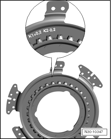
| 4th step: Determine clutch tolerance of clutch “K 1” |
| – |
Read clutch tolerance value from new clutch. |
| Example: Read off clutch tolerance value on clutch
“K 1 = +0.2”, as shown in diagram. |
| Result: Clutch tolerance of clutch “K 1” = + 0.20 mm. |
| 5th step: Determine thickness of shim “SK 1” |
Note
| On the basis of the clutch tolerance “K 1”, the thickness of
shim “SK1” is now calculated according to the following
calculus. |
|
|
|
| |
Height tolerance of engagement
bearing “K 1” |
| –/+ |
Clutch tolerance of clutch “K
1” |
| = |
Calculated thickness of shim “SK
1” |
| 2.42 mm + 0.20 mm = 2.62 mm |
| Result: Calculated thickness of shim “SK 1” = 2.62 mm |
|
|
|
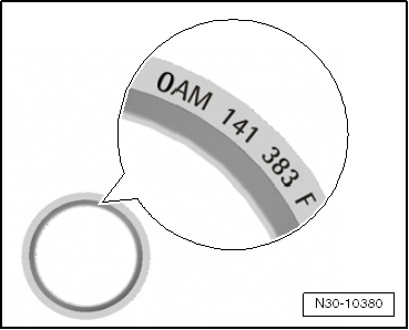
| – |
Select required shim from the table with the help of the
part number -magnifying glass- and
have it ready for installation. |
|
|
|
|
Calculated thickness of shim
mm |
Available shims
Thickness in mm |
Part
number of shim |
| 1.21 …
1.60 |
1.50 |
0AM 141
383 |
| 1.61 …
1.80 |
1.70 |
0AM 141
383 A |
| 1.81 …
2.00 |
1.90 |
0AM 141
383 B |
| 2.01 …
2.20 |
2.10 |
0AM 141
383 C |
| 2.21 …
2.40 |
2.30 |
0AM 141
383 D |
| 2.41 …
2.60 |
2.50 |
0AM 141
383 E |
| 2.61 …
2.80 |
2.70 |
0AM 141
383 F |
| 2.81 …
3.00 |
2.90 |
0AM 141
383 G |
| 3.01 …
3.20 |
3.10 |
0AM 141
383 H |
| 3.21 …
3.40 |
3.30 |
0AM 141
383 J |
| 3.41 … 3.80 |
3.50 |
0AM 141 383 K |
| Result: Calculated thickness of shim “SK 1” = 2.62 mm |
| Chosen shim thickness = 2.70 mm = part number 0AM 141 383 F |
Caution
| The clutch can be damaged. |
| Install only this shim later when required. |
|
|
|
|
| – |
Remove end gauge -T10466- and large engagement lever again. |
|
|
|
| 6th step: Determine dimension “A 2” for clutch engaging
lever “K 2” |
Note
| The upper section of bushing cannot be removed or installed
alone. It is always removed or installed together with lower
section of bushing and »small«
engagement lever. |
| Observe the following when installing a new engaging lever
»K2«: |
|
|
|
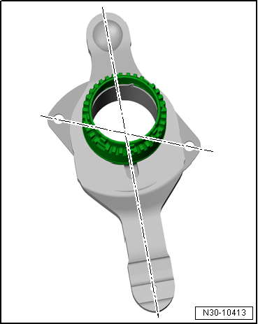
| The new engaging lever »K2« with
upper and lower section of guide sleeve will be delivered in
transport position -illustration-
and must be set to installation position prior to installation. |
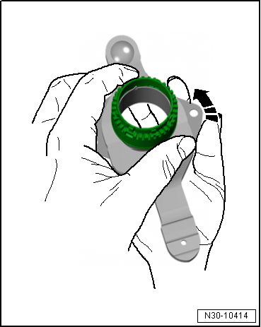
| Setting engaging lever »K2« to
installation position: |
|
|
|
| – |
Hold upper section of guide sleeve with one hand. With the
other hand turn the lower section of guide sleeve in direction
of arrow until the sleeve moves freely. |
Note
| Apply high force to hold both sections, as this is necessary
for turning the lower section of the guide sleeve. |
|
|
|
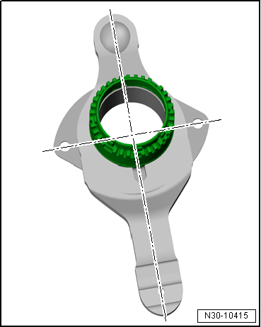
| If the engaging lever is in installation position, the holes
of the lower section of guide sleeve are at right angles to the
engaging lever. The sleeve moves freely. |
|
|
|
| – |
Install »small« engagement lever
together with upper and lower section of bushing. Insert and
tighten new bolts. |
| Specified torques:
→ Item |
|
|
|
| – |
Insert »small« engagement
bearing without shim. |
Caution
| Risk of false measurements. |
|
|
|
|
| Small engagement bearing only fits in one position due to 8
grooves. |
| – |
By turning, check whether small engagement bearing has been
installed correctly and that grooves are seated correctly. |
|
|
|
| – |
Place end gauge -T10466- on small engagement bearing. Flat
side faces upwards. |
| – |
To ensure that end gauge -T10466- sits properly on
engagement bearing, press down and turn end gauge. |
| Engagement bearing will turn with end gauge -T10466-. |
|
|
|
| – |
Place digital 300 mm depth gauge -VAS 6594- on top of ruler
and position depth gauge rod on outer input shaft. |
| Ruler -T40100- is lying upwards across end of shaft on
gearbox flange. |
Caution
| Risk of false measurements. |
| The ruler -T40100- should remain in this position
for the following measurements. Do not turn over, do not
remove. |
|
| – |
Set depth gauge to “0”. |
|
|
|
| – |
Position depth gauge rod on end gauge -T10466-, as show in
diagram. |
| – |
In this position, determine dimension “A 2a”
to end gauge -T10466-. |
| Example: Dimension “A 2a” = 4.79
mm |
|
|
|
| – |
In the opposite position, determine dimension “A 2b”
to end gauge -T10466-. |
| Example: Dimension “A 2b” = 4.75
mm |
| – |
Calculate mean value from dimension “A 2a”
and “A 2b”. |
| Result: Dimension “A 2” = 4.77 mm |
| 7th step: Calculate height tolerance of clutch engagement
bearing “K 2” |
Note
| On the basis of dimension “A 2” and dimension “B”, the
height tolerance of the engagement bearing for clutch “K 2” is
now calculated according to the following calculus. |
|
|
|
| |
Dimension “A 2” |
| – |
Dimension “B” |
| = |
Actual height tolerance of
clutch engagement bearing “K 2” |
| 4.77 mm – 2.60 mm = 2.17 mm |
| Result: Height tolerance of clutch engagement bearing “K 2”
= 2.17 mm |
|
|
|
| 8th step: Determine clutch tolerance of clutch “K 2” |
| – |
Read clutch tolerance value from new clutch. |
| Example: Read off clutch tolerance value on clutch “K 2 = –
0.2”, as shown in illustration. |
| Result: Clutch tolerance of clutch “K 2” = – 0.20 mm. |
| 9th step: Determine thickness of shim “SK 2” |
Note
| On the basis of the clutch tolerance “K 2”, the thickness of
shim “SK 2” is now calculated according to the following
calculus. |
|
|
|
| |
Height tolerance of engagement
bearing “K 2” |
| –/+ |
Clutch tolerance of clutch “K
2” |
| = |
Calculated thickness of shim “SK
2” |
| 2.17 mm – 0.20 mm = 1.97 mm |
| Result: Calculated thickness of shim “SK 2” = 1.97 mm |
| – |
Select required shim with help of table below and have it
ready for installation. |
|
|
|
|
Calculated thickness of shim
mm |
Available shims
Thickness in mm |
Part
number of shim |
| 0.31 …
0.90 |
0.80 |
WHT 005
518 |
| 0.91 …
1.10 |
1.00 |
WHT 005
518 A |
| 1.11 …
1.30 |
1.20 |
WHT 005
518 B |
| 1.31 …
1.50 |
1.40 |
WHT 005
518 C |
| 1.51 …
1.70 |
1.60 |
WHT 005
518 D |
| 1.71 …
1.90 |
1.80 |
WHT 005
518 E |
| 1.91 …
2.10 |
2.00 |
WHT 005
518 F |
| 2.11 …
2.30 |
2.20 |
WHT 005
518 G |
| 2.31 …
2.50 |
2.40 |
WHT 005
518 H |
| 2.51 …
2.70 |
2.60 |
WHT 005
518 J |
| 2.71 … 3.30 |
2.80 |
WHT 005 518 K |
| Result: calculated thickness of shim “SK 2” = 1.97 mm |
| Chosen shim thickness = 2.00 mm |
Caution
| The clutch can be damaged. |
| Install only this shim later when required. |
|
| The adjusting work has now been completed and the
»small« engagement lever has already
been installed. |
| – |
Install dual clutch
→ Chapter. |
|
|
|
Removing
Dual clutch removed
→ Chapter.
–
Remove large engaging lever with small engagement bea ...
© 2016-2026 Copyright www.vwgolf.org

 Removing and installing clutch engagement
 Clutch