Volkswagen Golf Owners Manual: Wheel bolts
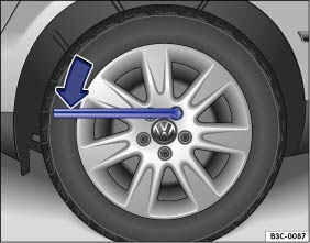
Fig. 222 Changing a wheel: loosening the wheel bolts
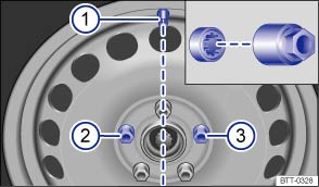
Fig. 223 Changing a wheel: tyre valve ① and locations of the anti-theft wheel bolt ② or ③
 First read and observe the introductory information
and safety warnings
First read and observe the introductory information
and safety warningsOnly the spanner delivered with the vehicle should be used to loosen the wheel bolts.
Only loosen the wheel bolts by approximately one turn before raising the vehicle with the vehicle jack.
If the wheel bolt is very tight, you may be able to loosen it by pushing down the end of the spanner carefully with your foot. Hold on to the car for support and take care not to slip.
Loosening the wheel bolts
- Fit the box spanner over the wheel bolt as far as it will go .
- Hold the end of the box spanner and turn the wheel bolt one turn anticlockwise .
Loosening the anti-theft wheel bolt
- Take the adapter for anti-theft wheel bolts out of the vehicle toolkit.
- Insert the adapter into the anti-theft wheel bolt. Push it in as far as it will go.
- Insert the box spanner into the adapter as far as it will go.
- Hold the end of the box spanner and turn the wheel bolt one turn anticlockwise .
Important information about the wheel bolts
The design of the wheel rims and wheel bolts is matched to the factory-fitted wheels. If different rims are fitted, the correct wheel bolts with the right length and correctly shaped bolt heads must be used. This ensures that wheels are fitted securely and that the brake system works properly.
In certain circumstances, wheel bolts from a vehicle of the same model series may not be used.
On wheels with a wheel cover, the anti-theft wheel bolt must be bolted into position or ③ according to the position of the tyre valve ①. Otherwise, it will not be possible to fit the wheel cover.
Tightening torque for the wheel bolts
The tightening torque for wheel bolts for steel and alloy wheels is 120 Nm. The tightening torque should be checked with a torque wrench immediately after changing a wheel.
If the wheel bolts are corroded and difficult to turn, they must be replaced and the wheel hub threads cleaned before the tightening torque is checked.
Never grease or lubricate the wheel bolts or the threads of the wheel hub. This could cause them to loosen while the vehicle is in motion, even if the required torque setting is used.

 WARNING
- Only use wheel bolts that belong to the wheel.
- Never use different wheel bolts.
- The wheel bolts and threads of the wheel hubs must be clean, free from oil and grease, and turn easily.
- Always use the box spanner placed in the vehicle at the factory to loosen and tighten the wheel bolts.
- Only loosen the wheel bolts by approximately one turn before raising the vehicle with the vehicle jack.
- Never grease or lubricate the wheel bolts or the threads of the wheel hub. This could cause them to loosen while the vehicle is in motion, even if the required torque setting is used.
- Never remove the bolts on rims with bolted-on rings.
- If the tightening torque of the wheel bolts is too low, the wheel bolts and rims can loosen while the vehicle is in motion. The wheel bolts and threads can be damaged if the tightening torque is too high.
 Checklist
The following actions must always be carried out in the given order
in preparation for changing the wheel :
In the event of a flat tyre, park your
vehicle on a firm and level surface at a s ...
 Lifting the vehicle with the jack
Fig. 224 Jacking points
Fig. 225 Vehicle jack at the rear left-hand
side of the vehicle
First read and observe the introductory information
and safety warningsThe jack may be applied only at t ...
Other materials:
Assembly overview - driver side airbag
1 -
Catch
To release, use a Torx screwdriver T25 of approx. 100 mm length
2 -
Steering column electronics control unit -J527-
With airbag coil connector and return ring with slip ring -F138-
Assembly overview
→ Elec ...
Removing and installing output module 2 for headlights,
»R«
WARNING
Risk of death due to high voltage! Risk of injury
and environmental pollution!
Observe operation and safety notes for gas discharge
bulbs
→ Chapte ...
Assembly overview - auxiliary heater attachments
1 -
Auxiliary heater
2 -
Clamping piece
3 -
Coolant hose
4 -
Air intake silencer
Removing and installing
→ Chapter
5 -
Bracket for ci ...
