Volkswagen Golf Service & Repair Manual: Removing engine
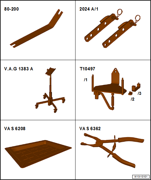
| Special tools and workshop equipment required |
| Extension -2024 A /1- of lifting tackle -2024 A- |
| Engine and gearbox jack -V.A.G 1383 A- or -VAS 6931- |
| Drip tray for workshop hoist -VAS 6208- |
| Hose clip pliers -VAS 6362- |
| Commercially available stepladder |
 Note Note
| The engine is removed downwards together with the gearbox. |
| Reinstall all cable ties in the same locations when
installing. |
The cooling system is under pressure when the engine is hot. Hot
steam/hot coolant can escape - risk of scalding. Risk of scalding to
skin and body parts.Wear protective gloves.Wear eye protection.Release
pressure by covering cap of coolant expansion tank with a cloth and
opening it carefully. |
|
|
| – |
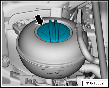
Open cap -arrow- on coolant
expansion tank. |
| – |
Remove left and right front wheel
→ Running gear, axles, steering; Rep. gr.44. |
| – |
Remove noise insulation
→ General body repairs, exterior; Rep. gr.66. |
| – |
Remove left and right front wheel housing liner
→ General body repairs, exterior; Rep. gr.66. |
| – |
Disconnect connector -2- from
radiator outlet coolant temperature sender -G83--3-. |
| – |
Set drip tray for workshop hoist -VAS 6208- underneath. |
|
|
|
| – |
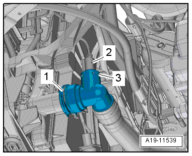
Lift retaining clip -1-,
disconnect coolant hose from radiator (bottom left) and drain
off coolant. |
 Note Note
| Do not reuse coolant which has been drained off. |
|
|
|
| – |
Lift retaining clip -arrow-,
disconnect coolant hose from water radiator (bottom right) for
charge air cooling circuit and drain off coolant. |
| – |
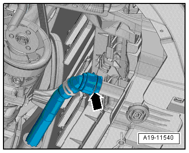
If poly V-belt is to be reinstalled, mark direction of
rotation on belt using chalk or felt tip pen before removing. |
| Vehicles with air conditioner compressor: |
|
|
|
| – |
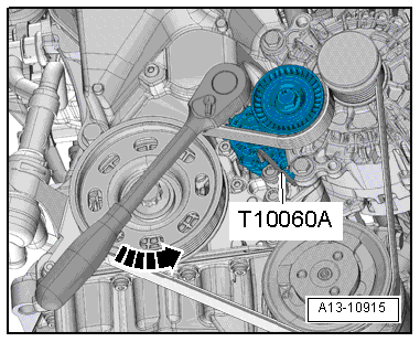
To slacken poly V-belt, swivel tensioning device in
anti-clockwise direction -arrow-,
and detach poly V-belt from pulley for air conditioner
compressor. |
| – |
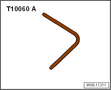
Lock tensioner with locking pin -T10060 A-. |
Risk of freezing injury caused by refrigerant.Do not open refrigerant
circuit of air conditioning system. |
|
|
| – |
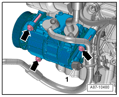
Disconnect connector -1- on air
conditioner compressor regulating valve -N280-. |
| – |
Remove bolts -arrows- for air
conditioner compressor. |
| – |
Detach air conditioner compressor from bracket (refrigerant
hoses remain connected) and tie up to right side. Do NOT
stretch, kink or bend refrigerant lines and hoses while doing
so. |
| Continuation for all vehicles: |
| – |
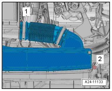
Release hose clip -1- and
detach air hose. |
|
|
|
| – |
Unscrew bolt -2- on left and
right. |
| – |
Unclip air duct at lock carrier and detach. |
|
|
|
| – |
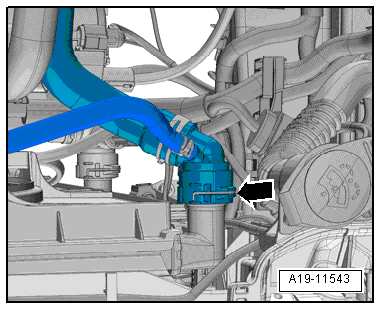
Lift retaining clip -arrow- and
disconnect coolant hose (top left) from radiator. |
|
|
|
| – |
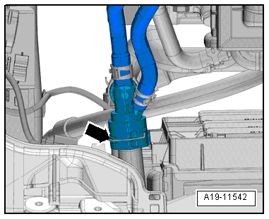
Lift retaining clip -arrow- and
disconnect coolant hose (top right) from water radiator for
charge air cooling circuit. |
|
|
|
| – |
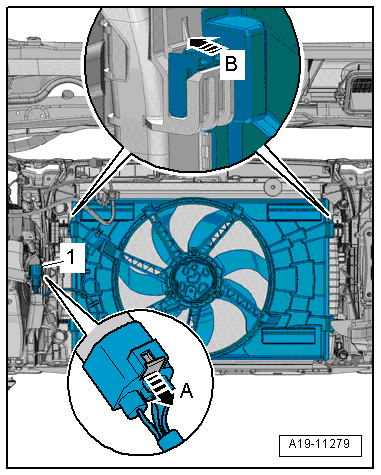
Unplug electrical connector -1-
for radiator fan (push retainer to the rear
-arrow A- and press down release
catch). |
| – |
Press locking tabs on left and right sides of radiator cowl
-arrow B- and at the same time lift
radiator cowl off radiator. |
| – |
Disconnect battery
→ Electrical system; Rep. gr.27. |
| – |
Remove battery and battery tray
→ Electrical system; Rep. gr.27. |
|
|
|
| – |
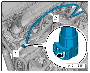
Release catch -arrow- and
disconnect vacuum hose -1-. |
| – |
Move clear vacuum hose at air pipe -2-. |
| Vehicles with no auxiliary heater |
|
|
|
| – |
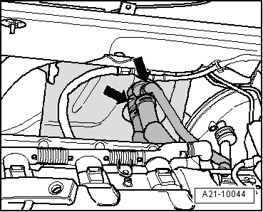
Lift retaining clips -arrows-
and disconnect coolant hoses from heat exchanger for heater. |
| Vehicles with auxiliary heater |
|
|
|
| – |
Release retaining clip and hose clip and pull off both
coolant hoses -arrows-. |
| Vehicles with engine preheater heater element -Z97- |
| – |
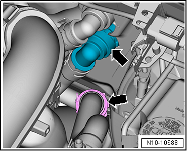
Unclip locking mechanism -arrow-. |
|
|
|
| – |
Pull off wiring -1- on engine
preheater heater element -Z97--2-. |
| – |
Unclip all cable ties from wiring harness
-1- on engine and secure wiring
harness on one side of the vehicle. |
| – |
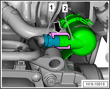
Pull off lower coolant hose on engine preheating element
-Z97- and remove coolant pipe. |
|
|
|
| – |
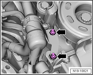
Unscrew nuts -arrows- and
remove engine preheating element -Z97- with bracket. |
| Continuation for all vehicles |
|
|
|
| – |
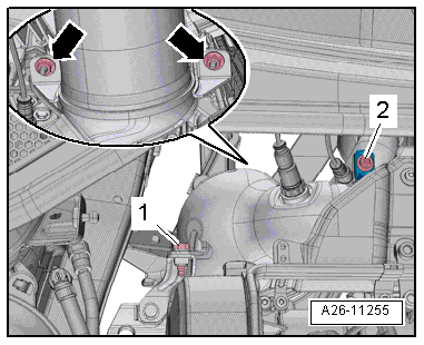
Unscrew bolt -2- and remove
screw-type clip. |
| – |
Remove bolt -1- and nuts
-arrows- and tie up catalytic
converter. |
|
|
|
| – |
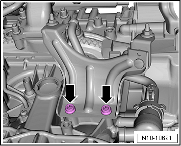
Undo bolts -arrow- and remove
bracket. |
 Note Note
| Place a cloth underneath to absorb escaping coolant. |
|
|
|
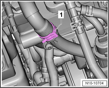
| Release hose clip -1- and pull
off coolant hose. |
The fuel system is pressurised.Risk of injury due to fuel which may
spurt out.Wear eye protection.Wear protective gloves.Release pressure:
place clean cloth around connection and carefully open connection.
| – |
Observe the rules for cleanliness when working on the fuel
supply system
→ Chapter. |
| – |
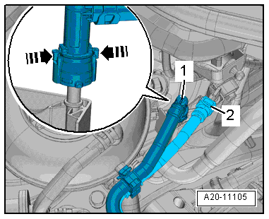
First press hose connector -1-
downwards, and then press release tabs
-arrows-. |
|
|
|
| – |
Keep release buttons pressed and pull off hose coupling. |
| – |
Press release tab on hose -2-
connected to activated charcoal filter. |
| – |
Disconnect hose and move it clear. |
| – |
Remove air filter housing
→ Chapter. |
 Note Note
|
|
|
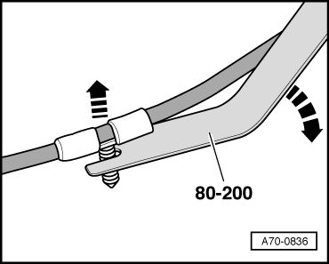
| For the work steps below use removal lever -80 - 200- to
unclip the binding clips. |
|
|
|
| – |
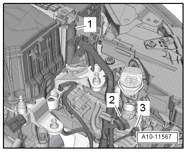
Unplug upper electrical connector -1-
at engine control unit -J623-
→ Chapter. |
| – |
Take electrical connectors -2-
and -3- out of retainer and detach. |
| – |
Move electrical lines free. |
|
|
|
| – |
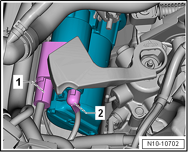
Disconnect electrical connector -2-. |
| – |
Push back cover for battery positive terminal
-1- and unbolt battery positive
cable from starter solenoid switch. |
| – |
Unbolt earth cable from body. |
|
|
|
| – |
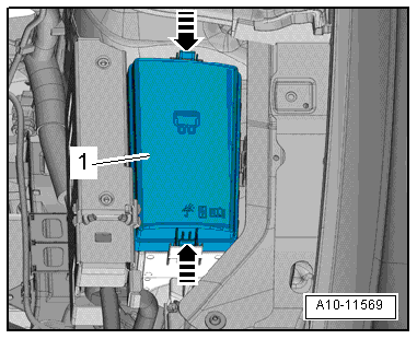
Release catches -arrows- and
detach cover -1- for electronics
box in engine compartment. |
|
|
|
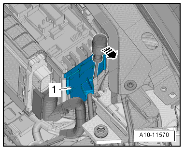
| – |
Release catch using a screwdriver
-arrow- and detach cover -1-
for electronics box in engine compartment upwards. |
|
|
|
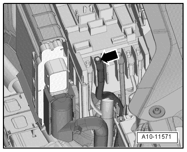
| – |
Remove nut -arrow-, detach
electrical wiring and move clear. |
|
|
|
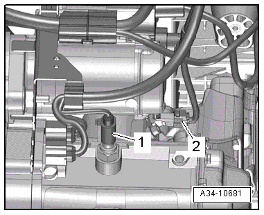
| – |
Disconnect electrical connectors -1-
and -2-. |
| – |
Remove selector mechanism from gearbox
→ Rep. gr.34. |
| – |
Remove clutch slave cylinder
→ Rep. gr.30. |
| – |
Remove selector lever cable, pull connector of mechatronic
off and remove all retainers from gearbox:
→ Rep. gr.34 |
| Continuation for all vehicles |
|
|
|
| – |
Unscrew bolts -arrows- on
engine mounting approx. 2 turns. |
|
|
|
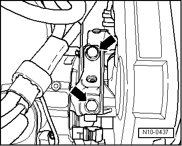
| – |
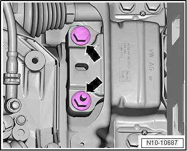
Unscrew bolts -arrows- on
gearbox mounting approx. 2 turns. |
|
|
|
| – |
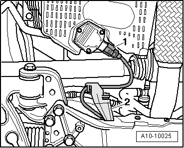
Disconnect electrical connector -1-
on oil level and oil temperature sender -G266-. |
| – |
Detach wire from retainer -2-. |
|
|
|
| – |
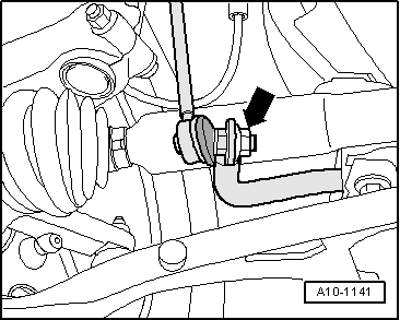
Unscrew nuts for coupling rod -arrow-
on left and right from anti-roll bar. |
|
|
|
| – |
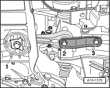
Unscrew bolts -1, 2 and 3-, and
remove pendulum support. |
|
|
|
| – |
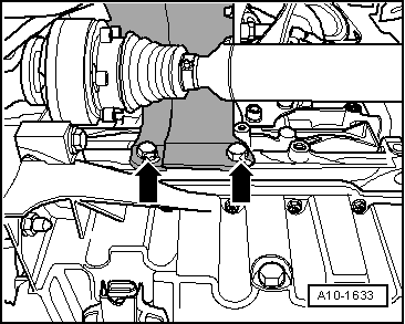
Unscrew bolts -arrows- and
remove heat shield for right drive shaft. |
|
|
|
| – |
Unscrew nuts -arrows- for
swivel joint on left and right. |
|
|

|
| – |
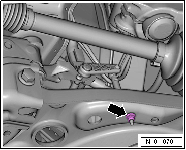
If fitted, remove nut -arrow-
from front left vehicle level sender -G78-. |
| – |
Detach swivel joint from transverse link on left and right. |
| – |
Unbolt drive shaft from gearbox on left and right, and tie
it up
→ Running gear, axles, steering; Rep. gr.40. |
 Note Note
| Take care not to damage the surface protection of the drive
shaft. |
|
|
|
| – |
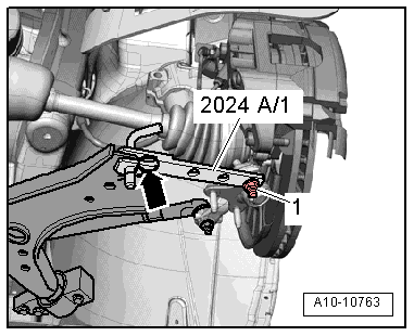
Swivel left suspension strut outwards and support it with
extension -2024 A /1- as shown in illustration. |
| – |
Secure locking pin and swivel joint with locating pin
-arrow- and nut
-1-. |
|
|
|
| – |
Secure swivel joint -2-
(right-side) to transverse link -1-
with nut -arrow-, as shown in
illustration. |
| – |
Apply clamping piece T10497/2 at housing rib on cylinder
block, as shown in illustration. |
| Vehicles with four-wheel drive |
| – |
Unbolt flexible coupling of propshaft from bevel box
→ Final drive, differential; Rep. gr.39. |
| Continuation for all vehicles |
|
|

|
| – |
Position engine support T10497 with pin T10497/1 on cylinder
block. |
| – |
Screw in bolt -1- through hole
“B” in engine support T10497 and tighten it to 20 Nm. |
|
|

|
| – |
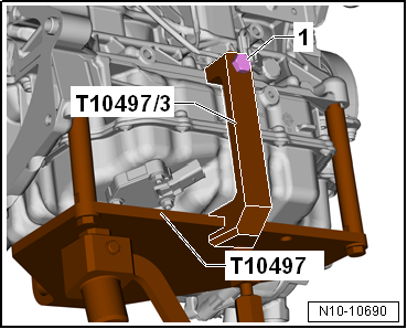
Fit adapter -T10497/3- to engine support -T10497- and
tighten bolt -1- to 20 Nm. |
| – |
Insert engine and gearbox jack -V.A.G 1383 A- in engine
support T10497 and raise engine/gearbox assembly slightly. |
 Note Note
| To unscrew bolts for assembly mounting use commercially
available stepladder. |
|
|
|
| – |
Remove bolts -arrows- for
engine mounting. |
|
|

|
| – |
Remove bolts -arrows- securing
gearbox mounting. |
 Note Note
| Danger of damage to vacuum lines or electrical wiring and to
engine compartment. |
| Check that all vacuum lines and electrical wiring between
engine, gearbox, subframe and body have been detached. |
| When lowering, carefully guide engine/gearbox assembly with
assembly carrier out of engine compartment. |
| – |
First lower engine/gearbox assembly slightly. |
| – |
Then push gearbox end of engine/gearbox assembly forwards
and only then lower further. |
|
|
 |
Special tools and workshop equipment
required
Shackle -10 - 222 A /12-
...
Other materials:
Seat heating
Fig. 53 In the centre console: buttons
for the front seat heating
First read and observe the introductory information
and safety warnings The seat cushions and backrests can be heated electrically
when the ignition is switched on. Some seat versions have heated backrests.
Do not switch o ...
Overview of fitting locations – control units, front of LHD vehicles
1 -
Data bus diagnostic interface -J533-
Assembly overview
→ Chapter
2 -
Bracket
Assembly overview
→ Chapter
3 -
Onboard supply control unit -J519-
...
Removing and installing front turn signal bulb -M5-/-M7- (gas discharge
headlights)
Note
Removal and installation are described for the left side.
Removal and installation on the right side are carried out in
the same way.
If the left turn signal bulb on vehicles with TDI engine
cannot be remo ...
© 2016-2026 Copyright www.vwgolf.org


 Note
Note Note
Note Note
Note Note
Note Note
Note Note
Note Note
Note Separating engine and gearbox


