Volkswagen Golf Service & Repair Manual: Removing and installing wheel bearing housing

| Special tools and workshop equipment required |
| Ball joint puller -3287A- |
| Ball joint puller -T10187- |
| Torque wrench -V.A.G 1332- |
| Engine and gearbox jack -V.A.G 1383 A- |
| Angle wrench -V.A.G 1756- |
| – |
Remove bolt for drive shaft
→ Chapter. |
 Caution
| Wheel bearings must not be subjected to load after
bolt securing drive shaft to wheel hub has been
loosened. |
| If wheel bearings are loaded with weight of vehicle,
bearing will be damaged. This reduces the service life
of the wheel bearing. |
| It is not permissible to loosen drive shaft bolt
more than 90° if vehicle is standing on its wheels. |
| Do not attempt to move the vehicle without the drive
shafts fitted as this would damage the wheel bearing. If
a vehicle nevertheless has to be moved, comply with the
following: |
| Install an outer joint instead of the drive shaft. |
| Tighten outer joint to 120 Nm. |
|
| – |
Detach brake caliper and tie to body with wire
→ Brake system; Rep. gr.46. |
| – |
Remove ABS speed sensor
→ Brake system; Rep. gr.45. |
| – |
Remove brake disc
→ Brake system; Rep. gr.46 |
| – |
Detach bracket for brake line and electrical wiring from
wheel bearing housing and move clear. |
|
|
|
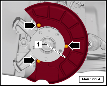
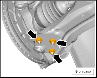
| – |
Remove splash plate -1- from
wheel bearing housing -arrows-. |
| – |
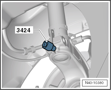
Loosen nut on track rod ball joint but do not remove
completely. |
|
|
|
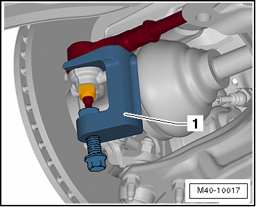
| – |
Press track rod off wheel bearing housing using ball joint
puller -T10187--1-. |
Caution
| Leave nut screwed on a few turns to protect thread
on pin. |
|
| – |
Unscrew nut, and remove track rod upwards from wheel bearing
housing. |
| Vehicles with vehicle level sender |
|
|
|
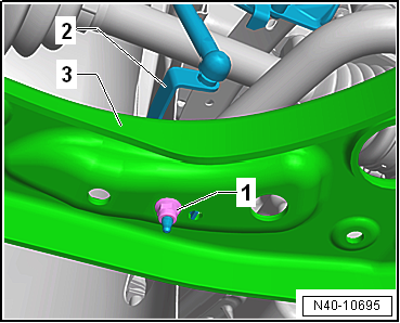
| – |
Pull bracket -2- for front left
vehicle level sender -G78- and/or for front right vehicle level
sender -G289- out of suspension link -3-,
as applicable |
| Continuation for all vehicles |
|
|
|
| – |
Pull swivel joint out of suspension link. |
| – |
Pull outer joint of drive shaft out of wheel hub. |
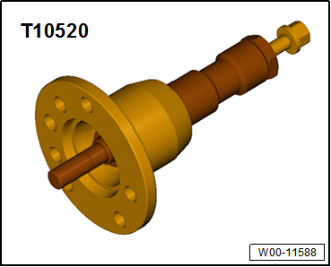
| If drive shaft cannot be pulled out of the wheel bearing by
hand, use press tool -T10520-. |
|
|
|
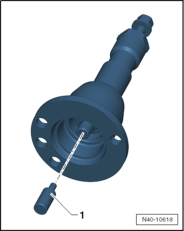
| Before using press tool -T10520- ensure that thrust piece
-1- is inserted. |
| Using press tool -T10520-: |
|
|
|
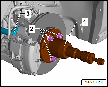
| – |
To be able to press out drive shaft
-3-, secure press tool -T10520--1-
to wheel hub using 3 wheel bolts -2-. |
|
|
|
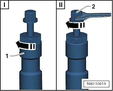
| – |
It is essential to follow specified sequence. |
| I - |
Tighten knurled nut -1-
hand-tight. |
| II - |
Turn only bolt -2- using a
spanner in order to press out drive shaft with press tool
-T10520-. |
 Note Note
| At the end of the procedure or for pressing out drive shaft
further the spindle must be moved to its original position in
order to deploy the hydraulic force! |
| – |
Secure drive shaft to body with wire. |
| – |
Position engine and gearbox jack -V.A.G 1383 A- under wheel
bearing housing. |
|
|
|
| – |
Remove threaded connection between wheel bearing housing and
suspension strut -arrow-. |
|
|

|
1 -
Splash plate
2 -
Bolt
12 Nm
3 -
Wheel bearing unit
Removing and installing
&# ...
Special tools and workshop equipment
required
Torque wrench -V.A.G 1332-
Removin ...
© 2016-2026 Copyright www.vwgolf.org

 Assembly overview - wheel bearing assembly
 Removing and installing wheel bearing unit