Volkswagen Golf Service & Repair Manual: Removing and installing wheel bearing unit
| Special tools and workshop equipment
required |
|
|
|
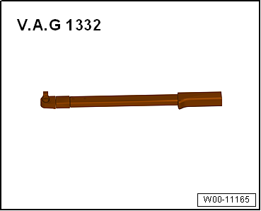
| Torque wrench -V.A.G 1332- |
| – |
Remove bolt for drive shaft
→ Chapter. |
 Caution
| Wheel bearings must not be subjected to load after
bolt securing drive shaft to wheel hub has been
loosened. |
| If wheel bearings are loaded with weight of vehicle,
bearing will be damaged. This reduces the service life
of the wheel bearing. |
| It is not permissible to loosen drive shaft bolt
more than 90° if vehicle is standing on its wheels. |
| Do not attempt to move the vehicle without the drive
shafts fitted as this would damage the wheel bearing. If
a vehicle nevertheless has to be moved, comply with the
following: |
| Install an outer joint instead of the drive shaft. |
| Tighten outer joint to 120 Nm. |
|
| – |
Detach brake caliper and tie to body with wire
→ Brake system; Rep. gr.46. |
| – |
Remove brake disc
→ Brake system; Rep. gr.46 |
|
|
|
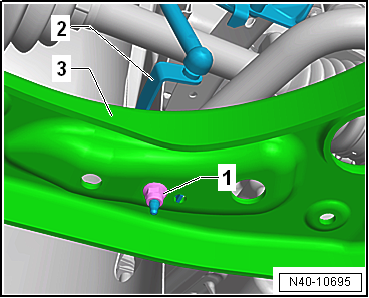
| Vehicles with vehicle level sender |
| – |
Pull bracket -2- for front left
vehicle level sender -G78- and/or for front right vehicle level
sender -G289- out of suspension link -3-,
as applicable |
| Continuation for all vehicles |
|
|
|
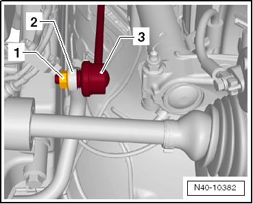
| – |
Unscrew nut -1- from coupling
rod -3-. |
| – |
Pull coupling rod -3- out of
anti-roll bar -2-. |
|
|
|
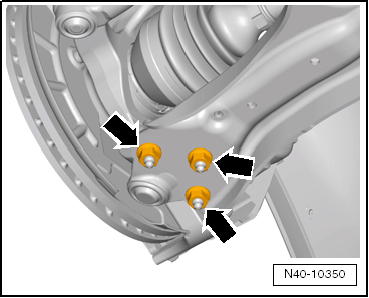
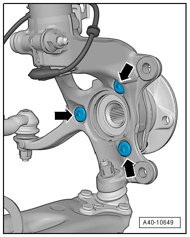
| – |
Pull swivel joint out of suspension link. |
| – |
Pull outer joint of drive shaft out of wheel hub. |
| – |
Secure drive shaft to body with wire. |
| – |
Bolt swivel joint to suspension link
-arrows- again. |
|
|
|
| – |
Take wheel bearing unit out of wheel bearing housing. |
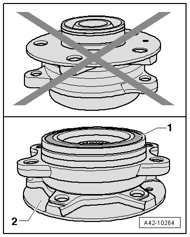
Caution
| Prevent damage to seal through soiling or when
mounting, storing or placing on a surface. |
|
|
|
|
| When placing wheel bearing unit down, wheel bearing
-1- must always face upwards. |
| Always set wheel bearing unit on hub
-2- when placing on a surface. |
|
|
|
| When picking wheel bearing up, never grasp inner side. |
| Grasp only outer side of wheel bearing. |
| Install in reverse order of removal, observing the
following: |
 Note Note
| Lever on vehicle level sender must face towards outside of
vehicle. |
| Thread of vehicle level sender must be screwed into outer
hole in suspension link. Retaining lug for vehicle level sender
must engage in inner hole in order to guarantee correct
installation position. |
| – |
On vehicles with vehicle level sender, carry out basic
settings for wheel damper electronics → Vehicle
diagnostic tester. |
| → Chapter „Assembly overview - wheel bearing assembly“ |
| → Chapter „Assembly overview - drive shaft“ |
| → Chapter „Assembly overview - subframe“ |
| → Chapter „Assembly overview - lower suspension link, swivel
joint“ |
| → Chapter „Assembly overview - front vehicle level senders“ |
| → Chapter „Torque settings for wheel bolts“ |
| Brake disc bolt
→ Brake system; Rep. gr.46 |
|
|

|
Special tools and workshop equipment required
Ball joint puller -3287A-
Spreader -3424-
Ball joint puller -T10187-
Torq ...
Other materials:
Removing and installing bonnet lock
Special tools and workshop equipment
required
Removing
Torque wrench -V.A.G 1331-
Note
If the rear lid does not open, it can be opened in a ...
Starting conditions for auxiliary heater, auxiliary heater mode
Auxiliary heater coded in Gateway
Reserve fuel level not reached
No crash shut-off
No event entries blocking start procedure
Has been put into servic ...
Introduction
This chapter contains information on the following subjects:
→ Folding the backrests on the rear bench seat forwards and backwards
→ Luggage compartment cover
→ Load-through hatch
→ Fastening rings
→ Bag hook
→ Luggage net ...
© 2016-2026 Copyright www.vwgolf.org

 Removing and installing wheel bearing housing
 Drive shaft