Volkswagen Golf Service & Repair Manual: Removing and installing valve stem seals (cylinder head installed)
| Special tools and workshop equipment
required |
|
|
|
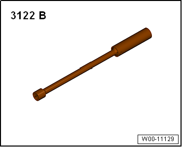
| Spark plug socket and extension -3122 B- |
|
|
|
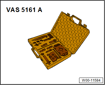
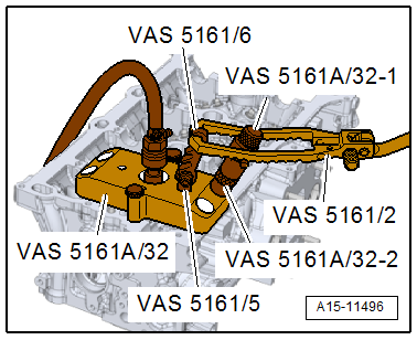
| Removal and installation device for valve cotters -VAS
5161A- with guide plate -VAS 5161A/32-32-. |
| Compressed air adapter -VAS 5161 A/35- (not illustrated) |
|
|
|
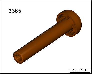
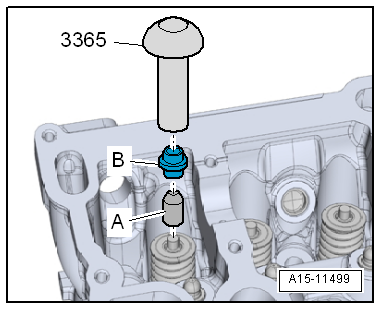
| Valve stem seal fitting tool -3365- |
|
|
|
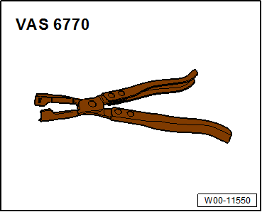
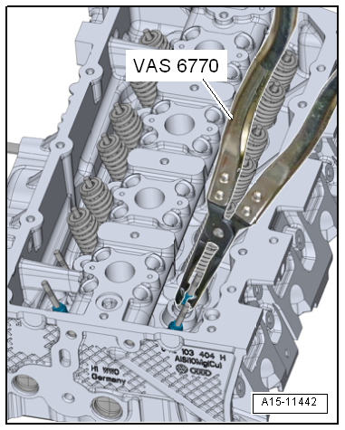
| Valve stem pliers -VAS 6770- |
| – |
Remove plenum chamber cover
→ Rep. gr.50. |
|
|
|
| – |
Remove plenum chamber bulkhead
→ Rep. gr.50. |
|
|
|
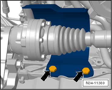
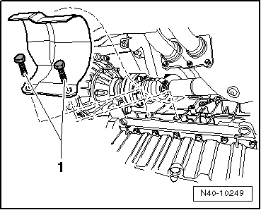
| – |
Remove bolts -arrows-. Remove
heat shield from right drive shaft. |
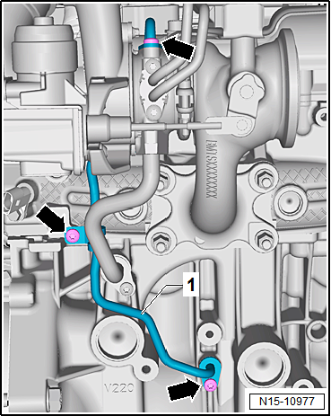
| – |
Unscrew bolts -arrows-, and
remove oil supply line -1-. |
| Continuation for all vehicles |
| – |
Remove camshaft housing
→ Chapter. |
| – |
Unscrew spark plugs with spark plug spanner -3122 B-. |
|
|
|
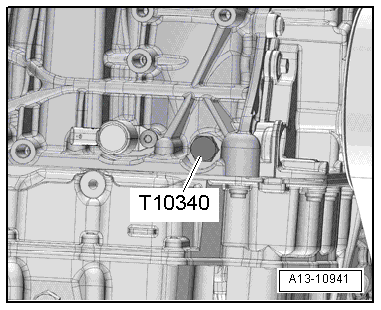
| – |
Unscrew locking pin -T10340-. |
| – |
Set piston of respective cylinder to “bottom dead centre”. |
|
|
|
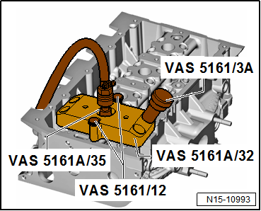
| – |
Fit guide plate -VAS 5161A/32-1- onto cylinder head and
secure with knurled screws -VAS 5161/12-. |
| – |
Screw compressed air adapter -VAS 5161 A/35- into the
respective park plug thread hand-tight. |
| – |
Connect adapter to compressed air supply using a
commercially available union and apply pressure continuously. |
| – |
Insert punch -VAS 5161/3A- into guide plate and use a
plastic hammer to knock loose the firmly seated valve cotters. |
|
|
|
| – |
Screw toothed piece -VAS 5161/6- with hooking fork
-VAS 5161/5- into guide plate. |
| – |
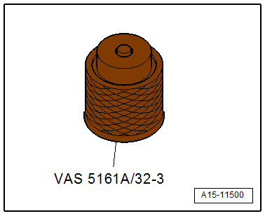
Slide sleeve -VAS 5161A/32-2- onto assembly cartridge and
insert cartridge into guide plate -VAS 5161A/32-3-. |
| – |
Attach pressure fork -VAS 5161/2- to toothed piece and press
assembly cartridge down. |
| – |
At the same time, turn knurled screw of assembly cartridge
clockwise until tips engage in valve cotters. |
| – |
Move knurled screw back and forth to press apart valve
cotters and capture them in assembly cartridge. |
| – |
Remove installation cartridge. |
| – |
Unbolt guide plate and move to side. |
| The compressed air hose remains connected. |
| – |
Remove valve spring and valve spring plate. |
|
|
|
| – |
Pull off valve stem seal using valve stem pliers -VAS 6770-. |
 Note Note
| Risk of damage when installing valve stem seals. |
|
|
|
| – |
Place plastic sleeve -A-,
enclosed with new valve stem seals -B-,
onto valve stem. |
| – |
Lightly oil sealing lip of valve stem seal. |
| – |
Push valve stem seal onto plastic sleeve. |
| – |
Carefully press valve stem seal onto valve guide using valve
stem seal fitting tool -3365-. |
|
|
|
| If the valve cotters have been removed from the assembly
cartridge, they must first be inserted into the insertion
device. |
| Larger diameter of valve cotters faces upwards. |
| – |
Press assembly cartridge onto insertion device from above
and pick up valve cotters. |
| – |
Insert valve spring and valve spring plate. For installation
position of valve spring refer to
→ Fig.. |
|
|
|
| – |
Bolt guide plate -VAS 5161A/32-1- onto cylinder head again. |
| – |
Insert assembly cartridge -VAS 5161A/32-2- with sleeve -VAS
5161A/32-3- into guide plate. |
| – |
Press pressure fork downwards and pull knurled screw
upwards, turning it clockwise and anticlockwise. This inserts
the valve cotters. |
| – |
Reduce pressure on pressure fork whilst pulling on knurled
screw. |
| – |
Repeat procedure on each valve. |
| Installation is carried out in the reverse order; note the
following: |
|
|
|
| – |
Install oil supply line -1-,
and tighten bolts -arrows- to 9 Nm. |
| – |
Install plenum chamber bulkhead
→ Rep. gr.50. |
| – |
Install plenum chamber cover
→ Rep. gr.50. |
| Continuation for all vehicles |
| – |
Install spark plugs
→ Booklet. |
| – |
Install camshaft housing
→ Chapter. |
|
|
|
| Component |
Specified
torque |
| Bolts -1- |
25 Nm |
Special tools and workshop equipment
required
Assembly tool -T10479 A-
Removing
...
Special tools and workshop equipment
required
Removal and installation device for valve cotters -VAS
...
© 2016-2026 Copyright www.vwgolf.org

 Removing and installing exhaust camshaft oil seal, gearbox end, engine codes
CHPA, CMBA, CPVA, CXSA, CZDA, CZCA, CPVB
Removing and installing exhaust camshaft oil seal, gearbox end, engine codes
CHPA, CMBA, CPVA, CXSA, CZDA, CZCA, CPVB Removing and installing valve stem seals (cylinder head removed)