Volkswagen Golf Service & Repair Manual: Removing and installing valve stem seals (cylinder head removed)
| Special tools and workshop equipment
required |
|
|
|
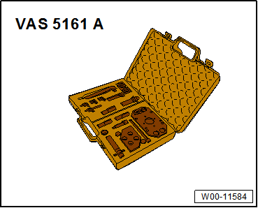
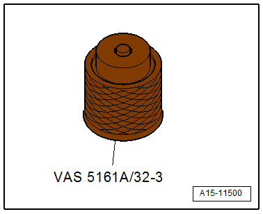
| Removal and installation device for valve cotters -VAS
5161A- with guide plate -VAS 5161A/32-32-. |
|
|
|
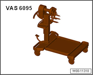
| Engine and gearbox support -VAS 6095- |
|
|
|
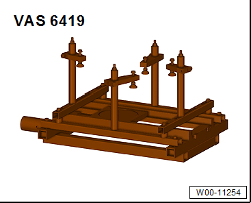
| Cylinder head tensioning device -VAS 6419- |
|
|
|
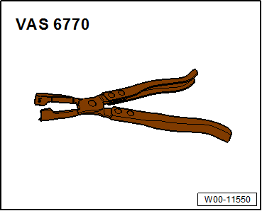
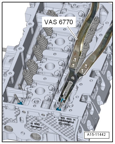
| Valve stem pliers -VAS 6770- |
|
|
|
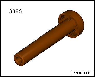
| Valve stem seal fitting tool -3365- |
|
|
|
| – |
Removing cylinder head
→ Chapter |
| – |
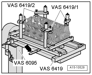
Insert cylinder head tensioning device -VAS 6419- into
engine and gearbox support -VAS 6095-. |
| – |
Tension cylinder head on cylinder head tensioning device as
shown in illustration. |
| – |
Connect cylinder head tensioning device to compressed air. |
| – |
Use lever -arrow- to slide air
cushion under combustion chamber from which valve stem seals are
to be removed. |
| – |
Allow compressed air to flow into air cushion until it lies
against valve disc. |
|
|
|
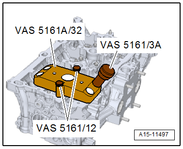
| – |
Fit guide plate -VAS 5161A/32-1- onto cylinder head and
secure with knurled screws -VAS 5161/12-. |
| – |
Insert punch -VAS 5161/3A- into guide plate and use a
plastic hammer to knock loose the firmly seated valve cotters. |
|
|
|
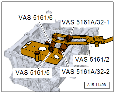
| – |
Screw toothed piece -VAS 5161/6- with hooking fork
-VAS 5161/5- into guide plate. |
| – |
Slide sleeve -VAS 5161A/32-2- onto assembly cartridge and
insert cartridge into guide plate -VAS 5161A/32-3-. |
| – |
Attach pressure fork -VAS 5161/2- to toothed piece and press
assembly cartridge down. |
| – |
At the same time, turn knurled screw of assembly cartridge
clockwise until tips engage in valve cotters. |
| – |
Move knurled screw back and forth to press apart valve
cotters and capture them in assembly cartridge. |
| – |
Remove installation cartridge. |
| – |
Unbolt guide plate and move to side. |
| – |
Remove valve spring and valve spring plate. |
|
|
|
| – |
Pull off valve stem seal using valve stem pliers -VAS 6770-. |
 Note Note
| Risk of damage when installing valve stem seals. |
|
|
|
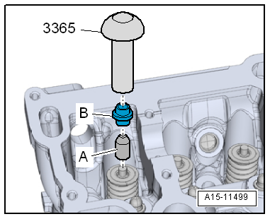
| – |
Place plastic sleeve -A-,
enclosed with new valve stem seals -B-,
onto valve stem. |
| – |
Lightly oil sealing lip of valve stem seal. |
| – |
Push valve stem seal onto plastic sleeve. |
| – |
Carefully press valve stem seal onto valve guide using valve
stem seal fitting tool -3365-. |
|
|
|
| If the valve cotters have been removed from the assembly
cartridge, they must first be inserted into the insertion
device. |
| Larger diameter of valve cotters faces upwards. |
| – |
Press assembly cartridge onto insertion device from above
and pick up valve cotters. |
| – |
Insert valve spring and valve spring plate. For installation
position of valve spring refer to
→ Fig.. |
|
|
|
| – |
Bolt guide plate -VAS 5161A/32-1- onto cylinder head again. |
| – |
Insert assembly cartridge -VAS 5161A/32-2- with sleeve -VAS
5161A/32-3- into guide plate. |
| – |
Press pressure fork downwards and pull knurled screw
upwards, turning it clockwise and anticlockwise. This inserts
the valve cotters. |
| – |
Reduce pressure on pressure fork whilst pulling on knurled
screw. |
| – |
Repeat procedure on each valve. |
| – |
Installing cylinder head
→ Chapter. |
|
|
|
Special tools and workshop equipment
required
Spark plug socket and extension -3122 B-
...
Other materials:
Receiver
The receiver collects the liquid droplets and directs them
in a continuous stream to the expansion valve. Moisture which
has entered the refrigerant circuit during assembly is collected
by the dessicant bag in the receiver.
Note
...
Conducting a road test before balancing wheels
If a customer brings a vehicle to the workshop complaining
about “vibration”, a road test is essential prior to balancing
the wheels.
This will give you information about the nature of the
vibration.
...
Assembly overview – special add-on parts, “R-Line”
1 -
Front bumper cover
“R Line”
→ Chapter
2 -
Emblems on radiator grille
“R Line”
→ Chapter
3 -
Rear lettering
“R Line”
→ Chapter
4&nb ...
© 2016-2026 Copyright www.vwgolf.org

 Removing and installing valve stem seals (cylinder head installed)