Volkswagen Golf Service & Repair Manual: General information
Repair instructions for repair work on ABS
| The ABS brake system is divided diagonally. The
servo-assistance is effected pneumatically by the vacuum brake
servo unit. |
| Vehicles with ABS are not fitted with a mechanical brake
pressure regulator. Specially developed software in the control
unit regulates the brake force distribution on the rear axle. |
 Note Note
| Faults in the ABS do not influence the brake system and
servo assistance. The conventional brake system remains
functional even without ABS. A change in braking behaviour is to
be reckoned with. After the ABS warning lamp comes on, the rear
wheels may lock prematurely during braking. |
|
|
|
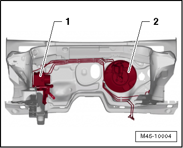
| ABS layout in LHD vehicles: |
| 1 - |
Hydraulic unit and control unit |
| The control unit and hydraulic are combined in a single
component. They can be separated only when removed. Hydraulic
pump must not be separated from hydraulic unit either. |
|
|
|
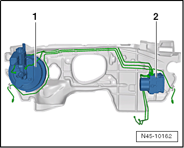
| ABS layout in RHD vehicles: |
| 1 - |
Brake servo and brake master cylinder |
| 2 - |
ABS hydraulic unit -N55- and ABS control unit -J104- |
| The control unit and hydraulic are combined in a single
component. They can be separated only when removed. Hydraulic
pump must not be separated from hydraulic unit either. |
| Before carrying out repair work on the anti-lock brake
system, determine the cause of the fault as well as the control
unit code using “Guided Fault Finding”. |
| “Guided fault finding” is carried out using
→ Vehicle
diagnostic tester. |
| Disconnect battery earth strap with ignition switched off. |
| Before carrying out welding work with an electric welding
unit, note
→ General Information; Body Repairs, General Body Repairs. |
| When working with brake fluid, observe the relevant safety
precautions and notes
→ Chapter. |
| After work for which the brake system had to be opened,
bleed the brake system with brake filling and bleeding equipment
-VAS 5234-
→ Chapter. |
| During the final road test, ensure that a controlled brake
test is performed at least once (pulsations must be felt at the
brake pedal). |
| Absolute cleanliness is required when working on the
anti-lock brake system. Auxiliary items containing mineral oil,
e.g. oils, greases, etc. must never be used. |
| Thoroughly clean all unions and the adjacent areas before
loosening. Do not use aggressive cleaning agents such as brake
cleanser, petrol, thinners or similar. |
| Place removed parts on a clean surface and cover. |
| If repairs cannot be carried out immediately, carefully
cover or seal open components. (Use sealing plugs from repair
kit 1 H0 698 311 A). |
| Only use lint-free cloths. |
| Only unpack replacement parts immediately prior to fitting. |
| Only use genuine packed parts. |
| When the system is open, do not work with compressed air and
do not move the vehicle. |
| The valve coils in the control unit cannot be adjusted. |
| The valve coils in the control unit cannot be renewed. |
| Pressure sensor must not be changed or damaged. |
| The pressure sensor cannot be renewed. |
| The sensor housing must not be exposed to mechanical stress. |
| No measurements must be taken on contact points of control
unit. |
| No measurements must be taken on contact points of hydraulic
unit. |
| Contact pins of hydraulic unit must not be bent or damaged. |
| The contacts cannot be renewed. |
| No contact sprays may be used on the contacts or the
pressure sensor. |
| Foreign bodies must not get between the control unit and the
hydraulic unit. |
| During painting operations, the electronic control unit can
be exposed to a maximum temperature of 95°C for only a short
period, and to a maximum of 85°C for longer periods (approx.
2 hours). During longer periods (2 hours), the control unit can
be exposed to a maximum temperature of 85°C. Ensure that no
brake fluid enters connectors. |
|
|
|
Overview of fitting locations - ABS/ESP
1 -
ABS control unit -J104-
Installation location: on hydraulic unit, on passenger side in
engine compartment.
...
© 2016-2026 Copyright www.vwgolf.org


 Overview of fitting locations