Volkswagen Golf Service & Repair Manual: Removing and installing steering rack, RHD vehicles, except for e-Golf
| Special tools and workshop equipment required |
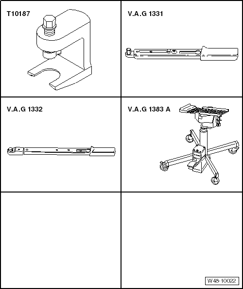
| Ball joint puller -T10187- |
| Torque wrench -V.A.G 1331- |
| Torque wrench -V.A.G 1332- |
| Engine and gearbox jack -V.A.G 1383 A- |
| – |
Turn steering wheel to straight-ahead position and remove
ignition key so that the steering lock engages. |
| Vehicles with keyless entry and start system “Keyless
Access” |
| – |
Switch off ignition and open driver's door so that the
steering lock engages. |
| – |
De-energise high-voltage system
→ Rep. gr.93. |
| Continuation for all vehicles |
| – |
Disconnect battery
→ Electrical system; Rep. gr.27. |
|
|
|
| – |
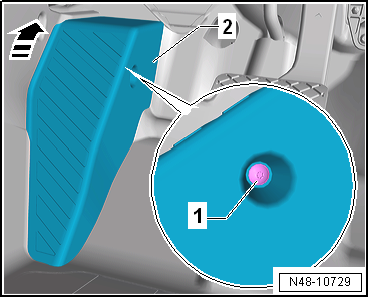
Push foot support -2- upwards
in -direction of arrow- and remove. |
| – |
Fold floor covering to the rear. |
|
|
|
| – |
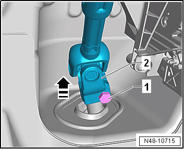
Unscrew bolt -arrow- from
universal joint -1- and pull off
universal joint in -direction of arrow-. |
 Caution
| The following work must not be performed while the
universal joint is separated from the steering rack: |
| Not adhering to these instructions will result in
irreparable damage. |
|
| – |
Remove lower noise insulation
→ General body repairs, exterior; Rep. gr.66. |
| For vehicles with natural gas engines |
|
|
|
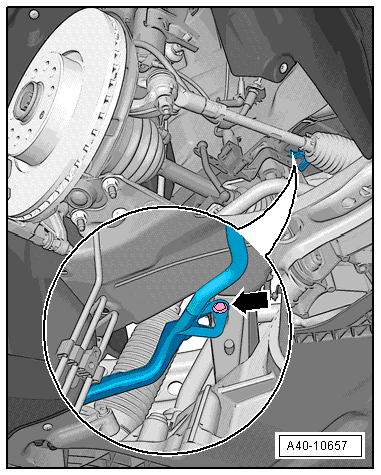
| – |
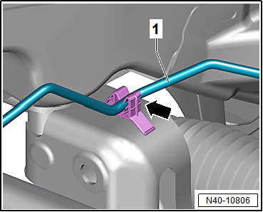
Unclip natural gas line -1-
from clip -arrow-. |
| Continuation for all vehicles |
|
|
|
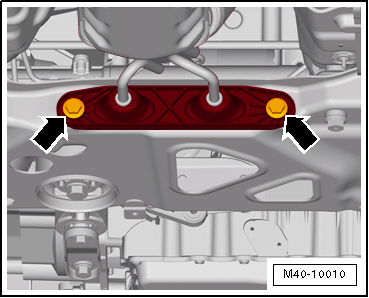
| – |
Detach exhaust system bracket from subframe
-arrows-. |
|
|
|
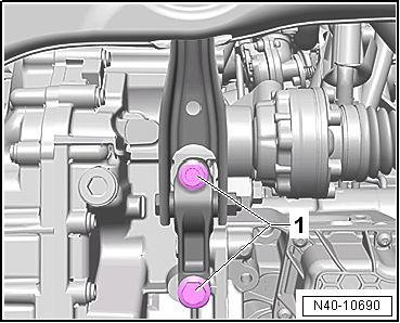
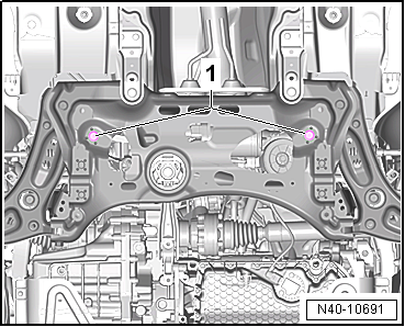
| – |
Unscrew bolts -1- for pendulum
support. |
|
|
|
| – |
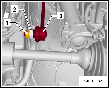
Unscrew nut -1- from coupling
rod -3- on both sides. |
| – |
Pull out coupling rod -3- from
anti-roll bar -2- on left and right
side. |
|
|
|
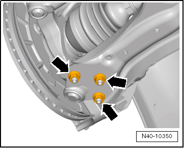
| – |
Remove nuts -arrows- on left
and right sides of vehicle. |
| – |
Pull swivel joint out of suspension link. |
|
|
|
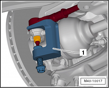
| – |
Using ball joint puller -T10187--1-,
press track rod ball joint off wheel bearing housing, and
unscrew nut. |
Caution
| Leave nut screwed on a few turns to protect thread
on pin. |
|
| Vehicles with vehicle level sender |
|
|
|
| – |
Disconnect connector -1- on
front left vehicle level sender -G78- and/or front right vehicle
level sender -G289-, as applicable. |
| Continuation for all vehicles |
|
|
|
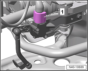
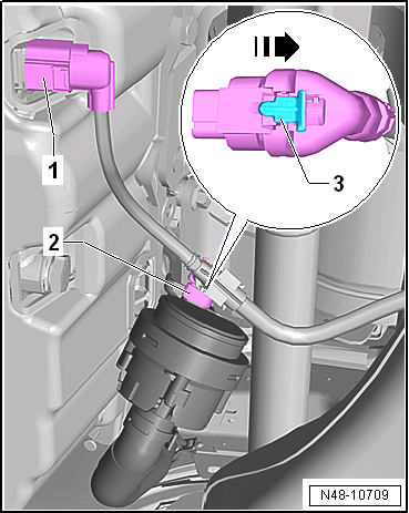
| – |
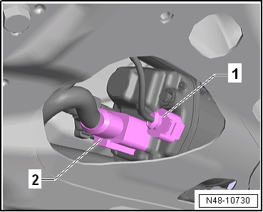
Disconnect connector -1- for
oil level and oil temperature sender -G266-. |
| – |
If fitted, disconnect connector -2-
on continued coolant circulation pump -V51-. Open locking
mechanism -3- in
-direction of arrow-, and release
connector. |
|
|
|
| – |
Pull wiring harness -3- clips
-1- and -2-
off subframe and steering rack. |
|
|

|
| – |
Remove bolts -1- for steering
rack. |
|
|
|
| – |
Position engine and gearbox jack -V.A.G 1383 A--1-
under subframe |
| – |
Fixing subframe
→ Chapter and lowering approx. 10 cm. |
|
|
|
| – |
Disconnect connectors -1- and
-2- from steering rack. |
|
|
|
| – |
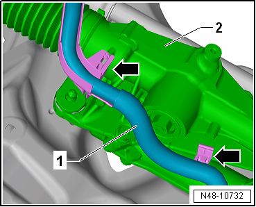
Unclip wiring harness -1- from
steering rack -2--arrows-. |
|
|
|
| – |
Pull out spreader clip -arrow-. |
| – |
Lower subframe with engine and gearbox jack -V.A.G 1383 A-. |
| – |
Prise steering rack off subframe, for example with a large
screwdriver, and remove to rear. |
|
|
|
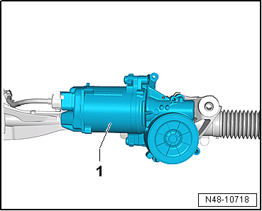
| – |
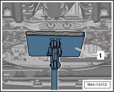
Place steering rack on a surface as shown. |
| This prevents damage to control unit
-1-. |
| Install in reverse order of removal, observing the
following: |
| Threaded sleeves of steering rack must seat in holes in
subframe. |
|
|
|
| – |
Plug in connectors -1- and
-2- so that they engage audibly. |
 Note Note
| Coat seal on steering rack with suitable lubricant, e.g.
soft soap, before installing steering rack. |
| After fitting the steering rack to the drive shaft ensure
that the seal is not kinked against the assembly plate on the
steering rack. The opening to the footwell must seal correctly.
Otherwise, this can result in water leaks and/or noise. |
| Ensure sealing surfaces are clean. |
|
|
|
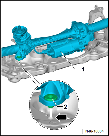
| – |
Position steering rack -1- on
subframe. |
| – |
Threaded sleeves -2- of
steering rack must be inserted in holes in subframe
-arrow-. |
|
|
|
Special tools and workshop equipment required
Ball joint puller -T10187-
Torque wrench -V.A.G 1331-
Torque wrench -V.A.G 1332-
...
Special tools and workshop equipment required
Hose clip pliers -V.A.G 1275-
Torque wrench -V.A.G 1332-
Tool insert 24 mm -V.A.G 133 ...
Other materials:
Radar sensor
Fig. 168 In the front bumper: radar sensor
First read and observe the introductory information
and safety warnings A radar sensor is fitted to the front bumper to monitor
the traffic situation . Vehicles travelling ahead can thus be detected up to a
distance of approximately 120 m.
T ...
Assembly overview - rear shelf support
Note
The illustration shows the rear shelf support on the left side. The
right-hand side is similar (mirror image of left-hand side).
1 -
Rear shelf support
Removing and installing
→ Chapter
2 -
Cli ...
COC document (EEC Certificate of Conformity)
Manufactures of motorized vehicles must apply for an EU
operating permit for all class M1 passenger carrying vehicles.
A certificate is produced on the basis of this operating
permit - the COC (Certificate of Conformity).
...
© 2016-2026 Copyright www.vwgolf.org

 Removing and installing steering rack, LHD vehicles, except for e-Golf
 Removing and installing boot