Volkswagen Golf Service & Repair Manual: Removing and installing intake manifold
| Special tools and workshop equipment
required |
| – |
Remove air filter housing
→ Chapter. |
| – |
Remove noise insulation
→ General body repairs, exterior; Rep. gr.66. |
| – |
Set drip tray for workshop hoist -VAS 6208- underneath. |
| – |
Drain coolant
→ Chapter. |
The fuel system is pressurised.Risk of injury due to fuel which may
spurt out.Wear eye protection.Wear protective gloves.Release pressure:
place clean cloth around connection and carefully open connection.
| Risk of functional impairment due to soiling
→ Chapter. |
|
|
|
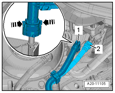
| – |
First press hose connector -1-
downwards, and then press release tabs
-arrows-. |
| – |
Keep release buttons pressed and pull off hose coupling. |
| – |
Press release tab on hose -2-
for activated charcoal filter. |
| – |
Disconnect hose and move it clear. |
|
|
|
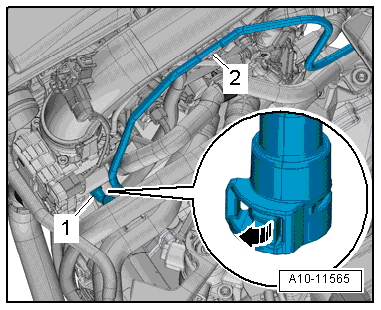
| – |
Release catch -arrow- and
disconnect vacuum hose -1-. |
| – |
Move clear vacuum hose at air pipe -2-. |
| – |
Move clear air hoses at charge air pipe. |
| – |
Detach connector from charge pressure sender -GX26-. |
|
|
|
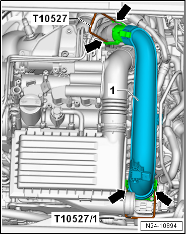
| – |
Release fasteners -arrows-
using release tools -T10527- and -T10527/1-. |
|
|
|
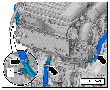
| – |
Unscrew bolt -1-, and release
clamps -arrows-. |
| – |
Pull off coolant hoses. |
|
|
|
| – |
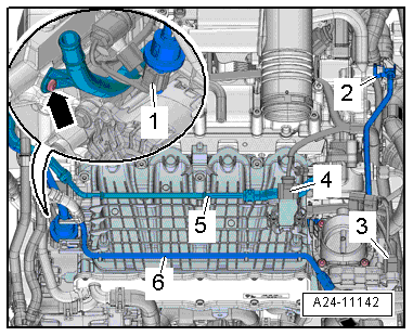
Separate electrical connectors: |
| 1 - |
For activated charcoal filter system solenoid valve 1 -N80-. |
| 3 - |
For throttle valve module -GX3-. |
| 4 - |
For intake manifold sender -GX9-. |
| – |
The -arrow- in the illustration
can be disregarded. |
| – |
Press release buttons and pull off hose
-2- for activated charcoal filter. |
| – |
Unclip fuel supply line -5- and
coolant line -6- from intake
manifold and push them to one side. |
|
|
|
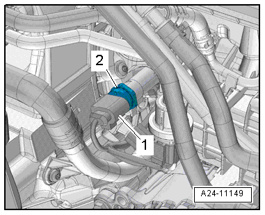
| – |
Disconnect connector -1- from
fuel pressure sender -G247-. |
| – |
Also disconnect connector from oil pressure switch. |
| – |
Loosen hose clamps -2- and pull
off coolant hoses. |
|
|
|
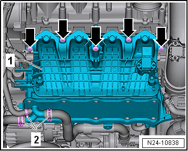
| – |
Remove intake manifold -1-. |
| Installation is carried out in the reverse order; note the
following: |
 Note Note
| – |
Install noise insulation
→ General body repairs, exterior; Rep. gr.66. |
| – |
Install air filter housing
→ Chapter. |
| – |
Replenish coolant
→ Chapter. |
| → Chapter „Assembly overview - intake manifold“ |
|
|
|
1 -
Coolant pipe
Clipped onto intake manifold.
Removing and installing coolant pipe
→ Chapter
2 -
...
Throttle valve module -GX3- consists of
Throttle valve module -J338-
Throttle valve drive for electronic power control - ...
© 2016-2026 Copyright www.vwgolf.org

 Assembly overview - intake manifold
 Removing and installing throttle valve module -GX3-