Volkswagen Golf Service & Repair Manual: Removing and installing fuel delivery unit/fuel gauge sender, vehicles with
front-wheel drive
| Special tools and workshop equipment
required |
|
|
|
| Torque wrench -V.A.G 1332- |
|
|
|
| – |
Observe safety precautions
→ Chapter. |
| – |
Observe rules for cleanliness
→ Chapter. |
| – |
Fuel tank must not be more than 3/4
full. This ensures that the fill level is below the flange of
the fuel delivery unit. |
| – |
Draining fuel tank
→ Chapter |
| – |
Remove right rear seat
→ General body repairs, interior; Rep. gr.72. |
|
|
|
| – |
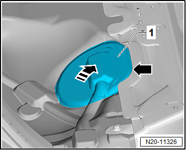
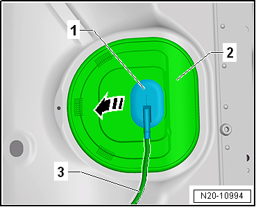
Partially detach cover -1- in
floor covering at parting line -arrow-. |
| – |
Do not detach cover completely from floor covering in order
to ensure it is reinstalled in the correct installation
position. |
| – |
Detach it just enough that the cover can be folded upwards. |
| – |
Fold up cover in -direction of arrow-. |
| – |
Remove rear bench seat
→ General body repairs, interior; Rep. gr.72. |
|
|
|
| Continuation for all vehicles: |
| – |
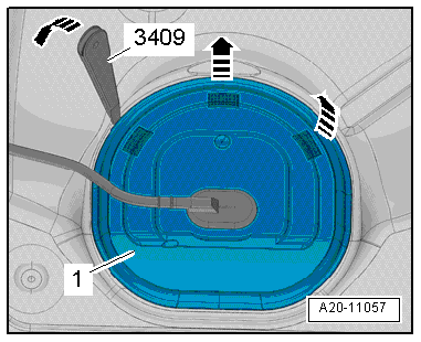
Unclip cover -1- for flange at
retaining tabs -arrows-, using
removal wedge -3409-. |
|
|
|
| – |
Unclip sealing grommet -1-
downwards from cover -2-. |
| – |
Push cover -2- back along
wiring harness -3-. |
|
|
|
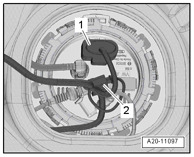
| – |
Release and pull off connector -1-
on sealing flange. |
| – |
If fitted, detach connector -2-
for metering pump -V54- of auxiliary heater on sealing flange
and lay connector aside. |
|
|
|
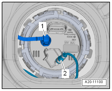
| – |
Disconnect fuel line -1- on
sealing flange. Separate plug-in connectors
→ Chapter. |
The fuel system is pressurised.Risk of injury due to fuel which may
spurt out.Wear eye protection.Wear protective gloves.Release pressure:
place clean cloth around connection and carefully open connection.
| – |
If fitted, remove fuel line -2-
leading to metering pump -V54- for auxiliary heater from sealing
flange. |
| – |
To do this, loosen lower hose clip. |
|
|
|
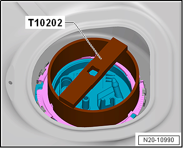
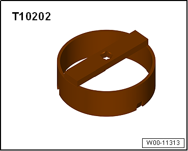
| – |
Open locking ring using wrench -T10202-. |
| – |
Carefully lift flange of fuel delivery unit. |
|
|
|
| – |
Insert dry seal -1- for fuel
delivery unit into opening in fuel tank. |
| – |
When inserting fuel delivery unit, ensure that fuel gauge
sender is not bent. |
| – |
Coat inner side of seal -1-
with fuel. |
| – |
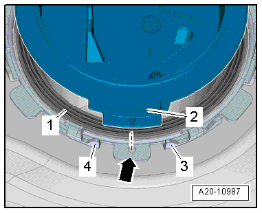
Press down sealing flange -2-
against spring force. |
| – |
Bring sealing flange to installation position. |
|
|
|
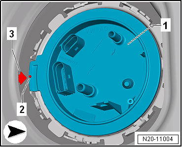
| – |
The arrow -3- on the fuel tank
must line up with the mark -2- on
the sealing flange -1-. |
| – |
When sealing flange is inserted, ensure that seal is not
damaged or squashed. |
|
|
|
| – |
Tighten locking ring using wrench -T10202-. |
|
|
|
| – |
Push fuel line -1- onto sealing
flange until it engages audibly. |
| – |
If present, install fuel line -2-
leading to metering pump -V54- for auxiliary heater on sealing
flange
→ Auxiliary heaters; Rep. gr.82. |
|
|
|
| – |
If present, attach connector -2-
for metering pump -V54- of auxiliary heater to sealing flange. |
| – |
Ensure connectors -1- are
firmly seated by pulling. |
| – |
After installing fuel delivery unit, fill fuel tank with at
least 5 litres of fuel. |
Risk of explosion of fuel tank caused by fuel pump activation.Risk of
severe injuries and burns.If a new or completely empty fuel tank has
been installed, fill it immediately with at least 5 litres of fuel.
| → Chapter „Assembly overview - fuel delivery unit and fuel gauge
sender“ |
|
|
|
1 -
Fuel delivery unit
With fuel system pressurisation pump -G6-.
With integrated fuel filter; fuel filter cannot be renewed
separately ...
Special tools and workshop equipment
required
Special wrench -T10202-
...
Other materials:
Operation
First read and observe the introductory information
and safety warnings The auxiliary heater exhaust system, located under the
vehicle, must not be blocked by snow, mud or other items. The exhaust fumes must
not be obstructed in any way. The emissions generated by the auxiliary heater are
...
Layout - infotainment system, standard display version
Display unit for control device of front display and
information control panel -J685-
Features of infotainment system standard display
5-inch monochrome touch screen
Support for ...
Assembly overview - front three-point seat belt, 2-door model
1 -
Bolt
If removed due to an accident with seat belt fastened, renew bolt.
20 Nm
2 -
Belt end fitting
Removing and installing
→ Chapter
3 -
Bolt
If removed due to an accident w ...
© 2016-2026 Copyright www.vwgolf.org

 Note
Note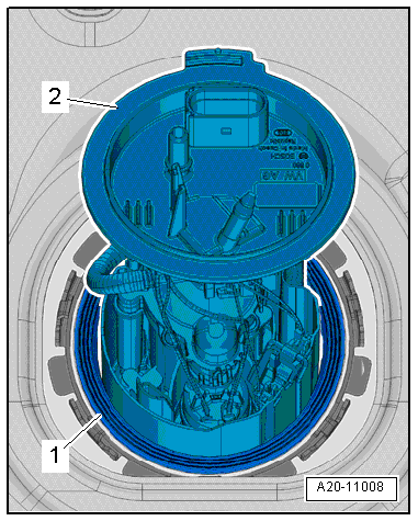
 Assembly overview - fuel delivery unit/fuel gauge sender, vehicles with
auxiliary heater
Assembly overview - fuel delivery unit/fuel gauge sender, vehicles with
auxiliary heater Removing and installing fuel delivery unit/fuel gauge sender, vehicles with
four-wheel drive
Removing and installing fuel delivery unit/fuel gauge sender, vehicles with
four-wheel drive