Volkswagen Golf Service & Repair Manual: Removing and installing driver side airbag igniter -N95-
| Special tools and workshop equipment
required |
| |
Commercially available Torx screwdriver T25 of approx. 100
mm length |
 WARNING
| |
Observe safety instructions for pyrotechnic
components
→ Chapter. |
| |
Observe disposal regulations for pyrotechnic
components
→ Chapter. |
|
| – |
Move steering wheel to rearmost and lowest position. |
| – |
Use the full adjustment range of the steering column
adjustment for this purpose. |
| – |
Remove upper steering column trim
→ Chapter. |
| – |
Turn steering wheel so that the opening on backside of
steering wheel is exactly in top position. |
|
|
|
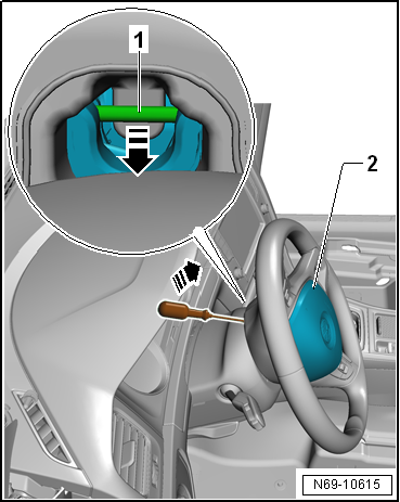
| – |
Release -arrows- locking
bracket -1- for driver side airbag
-2-. To do this, use a Torx
screwdriver T25 of approx. 100 mm length. |
 Note Note
| If a flat-bladed screwdriver is used, wires may become
damaged. |
| – |
Turn steering wheel through 180° and repeat procedure on
opposite side of steering wheel. |
| – |
Return steering wheel to mid-position (wheels pointing
straight ahead). |
|
|
|
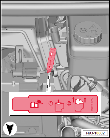
| – |
For “e-Golfs” or “Golf GTEs”, disconnect the maintenance
connector for high-voltage system -TW-. |
| – |
Disconnect battery earth cable with ignition switched on
→ Electrical system; Rep. gr.27. |
WARNING
| Before handling pyrotechnic components (e.g.
separating the electrical connector), the person
handling them must ensure that he/she is “electrically
discharged”. To do this e.g. briefly touch the door
striker plate. |
|
|
|
|
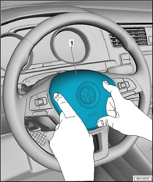
| – |
Position driver side airbag -1- in
steering wheel and push it in until it audibly engages. Hands must be
positioned on edges for this. |
WARNING
| Battery must be connected with ignition switched on.
If pyrotechnic components (e.g. airbag, seat belt
tensioners) are repaired incorrectly, undesired
triggering may occur after the battery is connected.
Ensure that nobody is in vehicle when connecting
battery. |
|
|
|
|
| – |
For “e-Golfs” or “Golf GTEs”, connect the maintenance
connector for high-voltage system -TW-. |
| – |
Connect battery earth cable with ignition switched on
→ Electrical system; Rep. gr.27. |
WARNING
| If the ignition has not yet been switched on after
the battery has been reconnected “warning lamps in dash
panel insert are off”, the ignition (key or button) must
only be switched on while sitting on the driver seat and
with the seat set to rearmost position. |
|
| – |
Finally, read and clear event memory of airbag control unit
since faults may be stored as a result of disconnecting
electrical connectors → Vehicle
diagnostic tester. |
| |
→ Chapter „Assembly overview - driver side airbag“ |
|
|
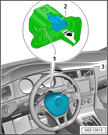
|
1 -
Catch
To release, use a Torx screwdriver T25 of approx. 100 mm length
2 -
Steering column electronics control unit -J527-
With ...
Removing
WARNING
Observe safety instructions for pyrotechnic
components
→ Chapter.
...
Other materials:
Changing gear using Tiptronic
Fig. 138 Selector lever in Tiptronic position
(left-hand drive). The controls are mirrored for right-hand drive vehicles
Fig. 139 Steering wheel with two paddles
for Tiptronic
First read and observe the introductory information
and safety warnings Using Tiptronic, the gears can be shifte ...
Fitting a bicycle carrier on the mechanically positioned ball coupling
First read and observe the introductory information
and safety warnings The maximum permitted load on a bicycle carrier mounted
on the ball coupling is 80 kg at a distance of 300 mm. This distance
refers to the gap between the centre of gravity of the bicycle carrier (complete
with bicycle ...
Fuse table
Fig. 230 In the dash panel: fuse layout
First read and observe the introductory information
and safety warningsThe table shows the fuse locations for the items of electrical
equipment which are most relevant to the customer. The left column contains the
location, the other columns contain t ...
© 2016-2026 Copyright www.vwgolf.org

 Assembly overview - driver side airbag
 Renewing connector on airbag