Volkswagen Golf Service & Repair Manual: Removing and installing drive shaft, right drive shaft, constant velocity
joints VL100 and VL107, except for e-Golf
| Special tools and workshop equipment
required |
|
|
|
| Torque wrench -V.A.G 1332- |
|
|
|
| – |
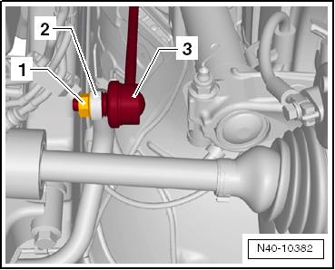
Unscrew nut -1- from coupling
rod -3-. |
| – |
Pull coupling rod -3- out of
anti-roll bar -2-. |
|
|
|
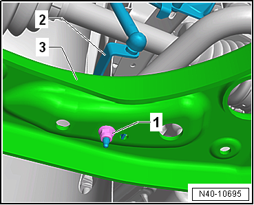
| Vehicles with vehicle level sender |
| – |
Pull bracket -2- for front left
vehicle level sender -G78- and/or for front right vehicle level
sender -G289- out of suspension link -3-,
as applicable |
| Continuation for all vehicles |
|
|
|
| – |
If fitted, remove bolts -1- and
detach heat shield -2-. |
| – |
Unbolt drive shaft from gearbox flange. |
|
|

|
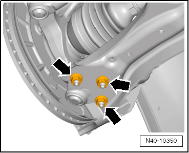
| – |
Unscrew nuts -arrows- on swivel
joint. |
| – |
Detach suspension link from swivel joint. |
| – |
Swivel suspension strut outwards and at the same time press
drive shaft out of wheel bearing unit. |
| If drive shaft cannot be pulled out of the wheel bearing by
hand, use press tool -T10520-. |
|
|
|
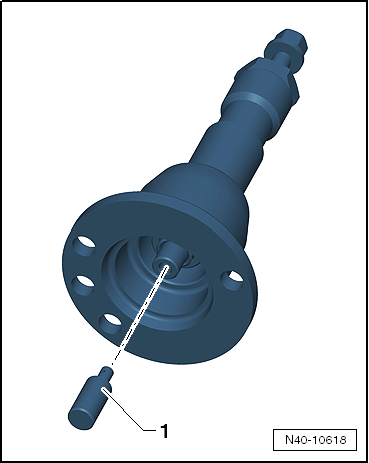
| Before using press tool -T10520- ensure that thrust piece
-1- is inserted. |
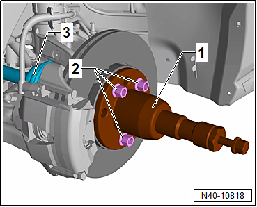
| Using press tool -T10520-: |
|
|
|
| – |
To be able to press out drive shaft
-3-, secure press tool -T10520--1-
to wheel hub using 3 wheel bolts -2-. |
|
|
|
Special tools and workshop equipment
required
Torque wrench -V.A.G 1332-
...
Special tools and workshop equipment
required
Torque wrench -V.A.G 1332-
...
Other materials:
Necessity of wheel alignment, multi-link suspension
Wheel alignment is necessary if:
The vehicle does not handle properly.
Vehicle has been involved in an accident and components have
been renewed.
Axle components are removed or renewed. ...
Expansion valve
The expansion valve atomises incoming refrigerant and
regulates the flow so that, depending on the heat transport, the
vapour does not become a gas until it reaches the outlet of the
evaporator.
...
Checking inertia reel (locking mechanism)
The inertia reel has two locking functions.
The first locking function is triggered by the belt being
jerked out of the reel (belt extension acceleration).
Test 1
–
Pull belt o ...
© 2016-2025 Copyright www.vwgolf.org

 Caution
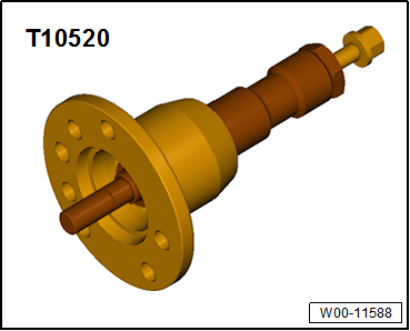
 Note
Note
 Removing and installing drive shaft, left drive shaft, constant velocity
joints VL100 and VL107, except for e-Golf
Removing and installing drive shaft, left drive shaft, constant velocity
joints VL100 and VL107, except for e-Golf Removing and installing drive shaft, left drive shaft, constant velocity
joints VL100 and VL107, e-Golf
Removing and installing drive shaft, left drive shaft, constant velocity
joints VL100 and VL107, e-Golf