Volkswagen Golf Service & Repair Manual: Removing and installing drive shaft, left drive shaft, constant velocity
joints VL100 and VL107, e-Golf
| Special tools and workshop equipment
required |
|
|
|
| Torque wrench -V.A.G 1332- |
|
|
|
| – |
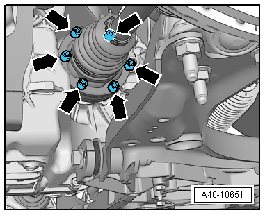
Unbolt drive shaft from gearbox flange shaft
-arrows-. |
| – |
Pull drive shaft out of wheel hub. |
| If drive shaft cannot be pulled out of the wheel bearing by
hand, use press tool -T10520-. |
|
|
|
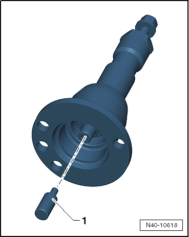
| Before using press tool -T10520- ensure that thrust piece
-1- is inserted. |
| Using press tool -T10520-: |
|
|
|
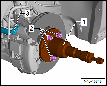
| – |
To be able to press out drive shaft
-3-, secure press tool -T10520--1-
to wheel hub using 3 wheel bolts -2-. |
|
|
|
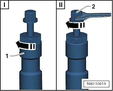
| – |
It is essential to follow specified sequence. |
| I - |
Tighten knurled nut -1-
hand-tight. |
| II - |
Turn only bolt -2- using a
spanner in order to press out drive shaft with press tool
-T10520-. |
 Note Note
| At the end of the procedure or for pressing out drive shaft
further the spindle must be moved to its original position in
order to deploy the hydraulic force! |
|
|
|
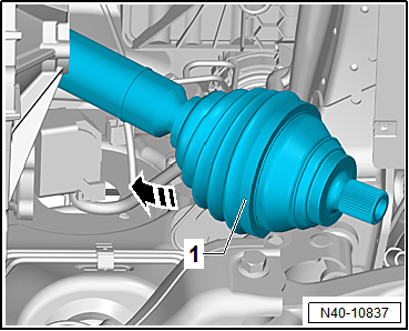
| – |
Remove drive shaft -1- from
wheel bearing, and swing it upwards in
-direction of arrow-. |
| – |
Remove drive shaft -1-
downwards. |
| Install in reverse order of removal, observing the
following: |
| Before fitting the outer joint in the wheel hub, apply a
thin coat of assembly paste to the splines on the outer joint
→ Electronic Parts Catalogue “ETKA”. |
| → Chapter „Assembly overview - drive shaft“ |
| → Chapter „Loosening and tightening threaded connections of
drive shaft“ |
| → Chapter „Torque settings for wheel bolts“ |
| Bolts for noise insulation
→ General body repairs, exterior; Rep. gr.66. |
|
|
|
Special tools and workshop equipment
required
Torque wrench -V.A.G 1332-
...
Special tools and workshop equipment
required
Torque wrench -V.A.G 1332-
...
© 2016-2024 Copyright www.vwgolf.org

 Caution
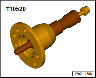
 Removing and installing drive shaft, right drive shaft, constant velocity
joints VL100 and VL107, except for e-Golf
Removing and installing drive shaft, right drive shaft, constant velocity
joints VL100 and VL107, except for e-Golf Removing and installing drive shaft, right drive shaft, constant velocity
joints VL100 and VL107, e-Golf
Removing and installing drive shaft, right drive shaft, constant velocity
joints VL100 and VL107, e-Golf