Volkswagen Golf Service & Repair Manual: Removing and installing control unit and hydraulic unit, RHD vehicles
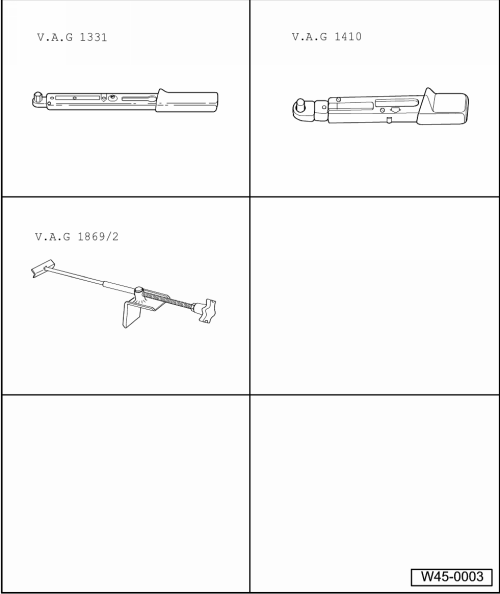
| Special tools and workshop equipment required |
| Torque wrench -V.A.G 1331- |
| Torque wrench -V.A.G 1410- |
| Brake pedal depressor -V.A.G 1869/2- |
| Sealing plugs, assembly part no. 5Q0 698 311 |
|
|
|
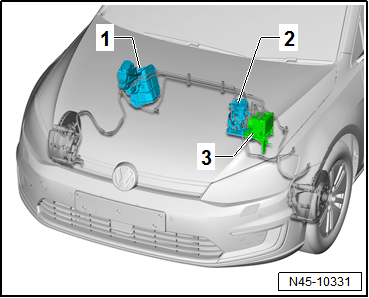
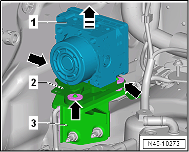
| The ABS control unit -J104- is bolted to the ABS hydraulic
unit -N55- and is located on the left of the engine compartment. |
| 1 - |
Brake servo and brake master cylinder |
| 2 - |
Brake system pressure accumulator -VX70- |
| 3 - |
ABS control unit -J104- with ABS hydraulic unit -N55- |
| Do not bend the brake lines in the area of the hydraulic
unit! |
| – |
Read out and note the existing control unit code. |
| – |
If vehicle has a coded radio, note radio code or, if
necessary, request it. |
| – |
Observe safety precautions when working on the high-voltage
system
→ Chapter. |
| – |
Observe the risk classification of the high-voltage system
→ Electric drive; Rep. gr.00. |
Danger to life due to high voltage.Risk of severe or fatal injury due to
electric shock.The high-voltage system must be de-energised by a
suitably qualified technician.
| – |
De-energise high-voltage system now
→ Electric drive; Rep. gr.93. |
| – |
Disconnect battery
→ Electrical system; Rep. gr.27. |
| – |
Remove brake system pressure accumulator -VX70-
→ Chapter. |
|
|
|
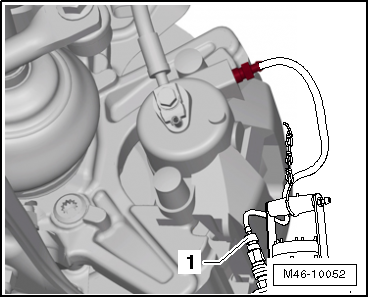
| – |
Press down retainer catch -arrow A-. |
| – |
Release electrical connector -arrow B-. |
| – |
Pull off electrical connector -1-. |
|
|

|
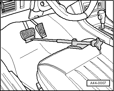
| – |
Apply brake pedal depressor -V.A.G 1869/2-. |
|
|
|
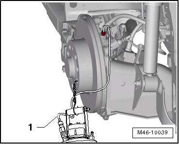
| – |
Connect hose of bleeder bottle -1-
to bleeder valve of front left brake caliper. |
|
|
|
| – |
Connect hose of bleeder bottle -1-
to bleeder valve of rear left brake caliper. |
| – |
Depress brake pedal at least 60 mm using brake pedal
depressor -V.A.G 1869/2-. |
| – |
Close front left and rear left bleeder valves. |
| – |
Do not remove brake pedal depressor -V.A.G 1869/2-. |
| – |
Place sufficiently lint-free cloths under ABS control unit
-J104- and ABS hydraulic unit -N55-. |
 Note Note
| Make sure no brake fluid gets onto electrical contacts on
ABS control unit -J104-. |
| – |
Unclip brake lines from plenum chamber bulkhead. |
|
|
|
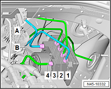
| – |
First, mark the two brake lines -A-
and -B- coming from brake master
cylinder. |
| – |
Unscrew both brake lines -A-
and -B- from ABS hydraulic unit
-N55-. |
| – |
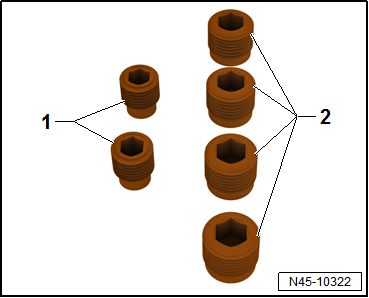
Seal threaded holes immediately using sealing plugs from the
assembly part kit, part no. 5Q0 698 311. |
|
|
|
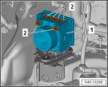
| – |
Mark, unscrew and seal threaded holes
-2- of remaining brake lines (brake calipers). |
|
|
|
| – |
Pull off ABS hydraulic unit -N55--1-
together with bracket -2- in
-direction of arrow-. |
| – |
The rubber dampers -arrows-
will be pulled off the studs of bracket
-3- while doing so. |
| – |
Guide hydraulic unit out of vehicle. |
| Install in reverse order. Note the following when doing
this: |
Note
| Remove sealing plugs from new hydraulic unit only when the
corresponding brake line is to be fitted. |
| If sealing plugs are removed too early from the hydraulic
unit, brake fluid can escape, and it can then no longer be
guaranteed that the unit can be sufficiently filled and bled. |
| Do not bend the brake lines in the area of the ABS hydraulic
unit -N55- |
| Ensure that rubber dampers of retainer are not pressed out
of bracket when installing. After installation, check that the
ABS hydraulic unit -N55- is firmly seated, or malfunction can
occur. |
|
|
|
| Tightening sequence of brake lines: |
| – |
First, attach and tighten brake lines in sequence
-4- to -1-. |
| – |
Then, attach and tighten brake lines in sequence
-A- to -B-. |
| – |
Remove brake pedal depressor -V.A.G 1869/2-. |
| – |
Bleed brake system
→ Chapter. |
| – |
Code control unit -J104- using → Vehicle
diagnostic tester in "Guided Fault Finding". |
| To do this, carry out basic setting of the steering angle
sender -G85-, the lateral acceleration sender -G200-, the
longitudinal acceleration sender -G251- and the brake pressure
sender -G201-. |
| Battery
→ Electrical system; Rep. gr.27 |
| Noise insulation
→ General body repairs, exterior; Rep. gr.66. |
| Front bleeder valves
→ Chapter „Assembly overview - front brake caliper“ |
| Rear bleeder valves
→ Chapter „Assembly overview - rear brake caliper“ |
Danger to life due to high voltage.Risk of severe or fatal injury due to
electric shock.The high-voltage system must be brought into operation by
a suitably qualified technician. |
|
|
Special tools and workshop equipment required
Torque wrench -V.A.G 1331-
Torque wrench -V.A.G 1410-
Brake pedal depressor -V.A.G 1869/2- ...
On hydraulic unit:
1 -
From hydraulic unit to rear right brake caliper
-
Identification: Ш 5.25&nb ...
Other materials:
Removing and installing tail light bulb -M2-/-M4-
Note
Removal and installation are described for the left side.
Removal and installation on the right side are carried out in
the same way.
Removing
–
Turn light switch to “0” position.
...
Assembly overview - condenser
Condenser, receiver
Note
The illustration shows the Modine condenser.
1 -
Condenser
Different versions. Refer to
→ Electronic Parts Catalogue.
Removing and installing
→ Cha ...
Vibration control system
Using the vibration control system -VAS 6230 A- you can
perform more functions than just stationary balancing.
A special feature of this system is the testing of the
radial force of the wheel and tyre while rolling.
A ro ...
© 2016-2026 Copyright www.vwgolf.org

 Removing and installing control unit and hydraulic unit, LHD
 Connecting brake lines to hydraulic unit, LHD vehicles