Volkswagen Golf Service & Repair Manual: Removing and installing brake servo, LHD vehicles
| Special tools and workshop equipment
required |
|
|
|
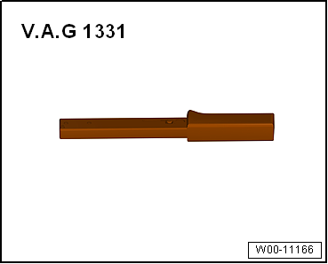
| Torque wrench -V.A.G 1331- |
|
|
|
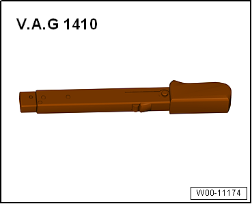
| Torque wrench -V.A.G 1410- |
| Tool inserts (11 mm) -V.A.G 1331/2- |
|
|
|
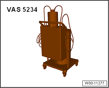
| Brake filling and bleeding equipment -VAS 5234- |
|
|
|
| Sealing plug repair kit -1H0 698 311 A- |
| Hot air blower, e.g. hot air blower -VAS 1978/14A- |
|
|
|
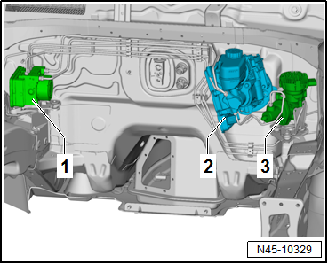
| 1 - |
ABS control unit -J104- and ABS hydraulic unit -N55- |
| 3 - |
Brake system pressure accumulator -VX70- |
| – |
Observe safety precautions when working in the area of
high-voltage components
→ Chapter. |
| – |
Observe the risk classification of the high-voltage system
→ Electric drive; Rep. gr.00. |
|
|
|
| Danger to life due to high voltage |
| The high-voltage system is under high voltage. If high-voltage
components are damaged, there is a risk of severe or fatal injury due to
electric shock. |
| – |
Carry out visual inspection of high-voltage components and cables. |
| – |
Never use cutting or forming tools, or any others with sharp edges. |
| – |
Never use heat sources such as welding, soldering, thermal bonding
or hot air. |
| – |
Read and note code of brake servo control unit -J539-
→ Vehicle diagnostic tester. |
| – |
Disconnect battery
→ Electrical system; Rep. gr.27. |
| – |
Remove power and control electronics for electric drive
-JX1-
→ Electrical system; Rep. gr.93. |
| – |
Remove bracket for power and control electronics for
electric drive -JX1-
→ Electrical system; Rep. gr.93. |
| – |
Release high-voltage cables from bracket and lay to side
→ Electrical system; Rep. gr.93. |
| – |
Remove bracket for high-voltage cables on the gearbox. |
|
|
|
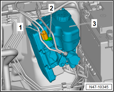
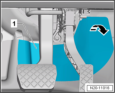
| – |
Release and pull off connector -1-
for brake fluid level warning contact -F34--2-
on brake fluid reservoir -3-. |
|
|
|
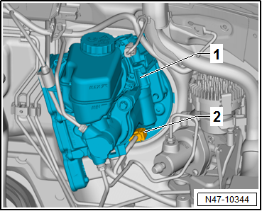
| – |
Release connector -2- and pull
it off brake servo -1-. |
|
|
|
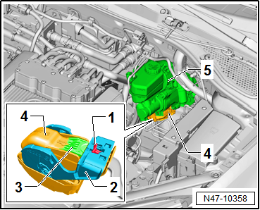
| – |
Pull locking slide (red) -1-
towards front. |
| – |
Press release tab -3- on
connector -4-. |
| – |
Release latch -2- and pull
connector -4- off brake servo
-5-. |
| Ensure no brake fluid gets onto contacts. |
| – |
Place sufficient lint-free cloths in area of engine,
subframe and gearbox. |
| Never allow brake fluid to come into contact with fluids
that contain mineral oils (e.g. oil, petrol, cleaning agents).
Mineral oils damage the plugs and seals in the brake system. |
| Brake fluid is poisonous and must never be sucked out by
mouth through a hose. Because of its caustic properties, it must
also not come into contact with paintwork. |
| Do not reuse drawn-off brake fluid. |
| Always observe the relevant environmental regulations for
disposal. |
| – |
Remove dash panel trim in driver footwell
→ General body repairs, interior; Rep. gr.68. |
|
|
|
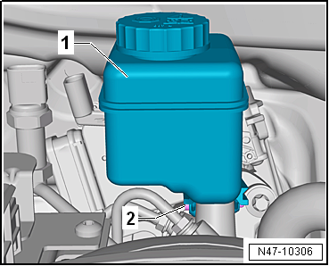
| – |
Fold down floor covering -1- in
-direction of arrow-. |
|
|
|
| – |
Unscrew bolt -2- and carefully
pull off brake fluid reservoir -1-
upwards. |
|
|
|
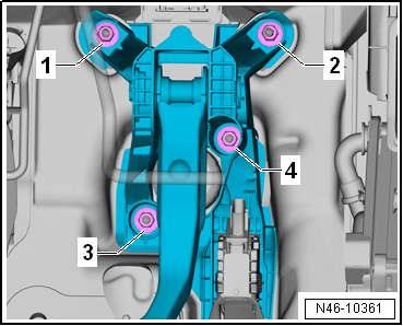
| – |
Mark position of brake lines -2 to 4-
on brake master cylinder -1-. |
| – |
Unscrew brake lines -2 to 4-
from brake master cylinder -1-. |
| – |
Immediately seal brake lines and open connections with
sealing plugs from repair kit -1H0 698 311 A- or suitable plugs
from engine bung set -VAS 6122-. |
| – |
Unscrew brake line -2- from
brake system pressure accumulator -VX70- and remove it. |
|
|

|
| – |
Unscrew nuts -3 and 4- from
brake servo. |
| – |
If brake servo gets jammed in holes, loosen both remaining
nuts -1 and 2- on the mounting
bracket. |
| – |
Carefully pull brake servo off plenum chamber bulkhead. |
| – |
Carefully remove brake servo from the vehicle. |
|
|
|
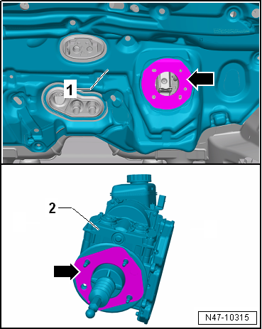
| – |
Remove adhesive residue -arrows-
from brake servo -2- and plenum
chamber bulkhead -1-. |
| – |
To do so, apply gentle heat from hot air blower to the
adhesive residue and pull it off. |
| – |
Thoroughly clean surfaces. |
| Install in reverse order. Note the following points: |
| – |
Renew seal between brake servo and plenum chamber bulkhead
→ Item. |
| – |
Carefully insert brake servo and tighten nuts hand-tight. |
| – |
Connect brake pedal to brake servo
→ Chapter. |
| – |
Bleed brake system
→ Chapter. |
| – |
Subsequently bleeding the brake system
→ Chapter. |
| – |
Code brake servo control unit -J539-
→ Vehicle diagnostic tester. |
| – |
Perform basic setting for electromechanical brake servo
→ Vehicle
diagnostic tester. |
| → Chapter „Assembly overview - brake servo/brake master
cylinder, LHD vehicles“ |
| → Chapter „Assembly overview – Brake system pressure accumulator
-VX70-“ |
| → Electrical system; Rep. gr.93 |
| → Electrical system; Rep. gr.27. |
| → General body repairs, interior; Rep. gr.68 |
| → Running gear, axles, steering; Rep. gr.48. |
|
|
|
Special tools and workshop equipment
required
Torque wrench -V.A.G 1331-
...
Special tools and workshop equipment
required
Torque wrench -V.A.G 1331-
...
Other materials:
Assembly overview - rear window washer system, Golf
1 -
High-level brake light
2 -
Connection for washer fluid hose
For rear window washer system.
3 -
Spray jet
Removing and installing
→ Chapter
Adjusting ...
Introduction
This chapter contains information on the following subjects:
→ Display and warning and indicator lamp
→ Operating the speed limiter
The speed limiter helps the driver not to exceed an individual stored speed when
driving forwards at speeds of approximately 30 km/h (20 m ...
Removing and installing front passenger side window regulator button -E716-
Note
The removal and installation procedures are described for
LHD vehicles. Removal and installation for RHD vehicles are
similar.
Removing
–
Remove front door trim panel
→ ...
© 2016-2026 Copyright www.vwgolf.org

 Note
Note Removing and installing brake system pressure accumulator -VX70-, RHD
vehicles
Removing and installing brake system pressure accumulator -VX70-, RHD
vehicles Removing and installing brake servo, right-hand drive vehicle