Volkswagen Golf Service & Repair Manual: Front camera for driver assist systems
Calibrating front camera for driver assist systems
 Note Note
| The following situations can cause the camera function to be
impaired by sustained poor visibility of the lane marker lines: |
| The field of view of the camera is soiled or iced over. In
this case, clean the affected area. |
| The field of view of the camera is fogged over. |
| The camera aperture must be cleaned manually if there is
heavy soiling on the inside of the windscreen in the field of
view of the camera. To do this, the control unit and lens hood
must be removed and the windscreen cleaned using cleaning
solution. Remove control unit and lens hood
→ Electrical system; Rep. gr.96. |
| Correct calibration is a basic precondition for the front
camera for driver assist systems -R242- to function without
faults. |
| The front camera for driver assist systems -R242- must be
recalibrated if: |
| ŌĆ£No or incorrect basic setting/adaptationŌĆØ entry stored in
the event memory. |
| The front camera for driver assist systems -R242- was
replaced. |
| Windscreen has been renewed or removed. |
| Rear axle toe setting has been adjusted. |
| Modifications have been made to the car's running gear that
have an effect on the body height. |
| Vehicle level senders are re-taught in vehicles with damping
control. |
Note
| Before calibrating the front camera for driver assist
systems, read out event memory and rectify faults as necessary. |
| Calibration of the front camera for driver assist systems
must only be performed using VW/AUDI approved wheel alignment
equipment! |
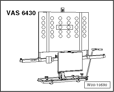
| Calibration of the driver assistant system's front camera is
only permitted using the setting device -VAS 6430-! |
| Special tools and workshop equipment
required |
|
|
|
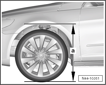
| ŌĆō |
Measure standing height at all four wheels and note it. |
Note
| Setting device -VAS 6430- is not allowed to be moved on
alignment beam. |
| Wheel alignment platform must be in the lowermost levelled
position for next work step. |
|
|
|
| ŌĆō |
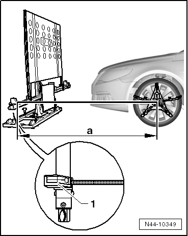
Turn setting device -VAS 6430- upwards so that alignment
beam is parallel to middle of measurement transducers on front
wheels, in order to perform a correct measurement with distance
measuring unit -1-. |
| 1 - |
Distance measuring unit with tape measure and socket pin |
| ŌĆō |
Position setting device -VAS 6430- at distance
-a- of 1500 mm ┬▒ 25 mm from centre
point of hub of front wheels to beam of setting device -VAS
6430-. |
 Caution
| Distance -a- of 1500 mm
┬▒ 25 mm must be measured on both sides of vehicle and
setting device -VAS 6430- must then be aligned. |
| Distance -a- must be
same on both sides of car. |
|
|
|
|
| ŌĆō |
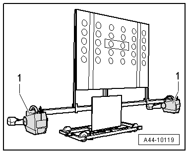
Mount measurement transducer -1-
of front wheels onto setting device -VAS 6430-. |
|
|
|
| ŌĆō |
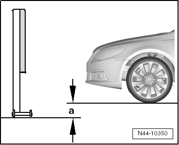
Measure height value -a-
between standing surface of setting device -VAS 6430- and wheel
support surface on wheel alignment platform. Enter value in
wheel alignment computer. |
|
|
|
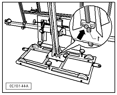
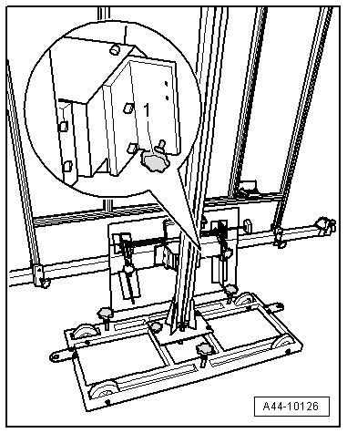
| ŌĆō |
Unscrew clamping bolt -arrow-,
place measuring bar -1- on floor. |
|
|
|
| ŌĆō |
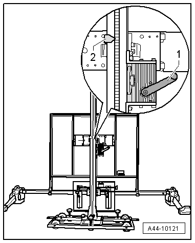
Use crank -1- to set
calibration panel -VAS 6430/4- to nominal height
-2- indicated by wheel alignment
computer and make a note. |
|
|
|
| When nominal height has been reached, measuring bar
-1- must be moved upwards slightly
and secured with clamping screw -arrow-. |
|
|
|
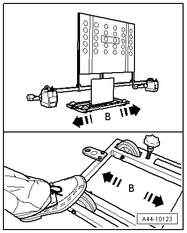
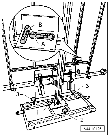
| ŌĆō |
Move setting device -VAS 6430- sideways
-arrows B- until display on wheel
alignment computer is within tolerance. |
|
|
|
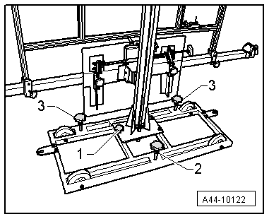
| ŌĆō |
Screw down adjuster screws -2-
and -3- slightly to secure setting
device -VAS 6430- against rolling away. |
|
|
|
| ŌĆō |
Turn fine adjuster screw -1-
until display on wheel alignment computer is within tolerance. |
|
|
|
| ŌĆō |
Use adjuster screw -1- to level
spirit level -A-. |
|
|
|
| ŌĆō |
Use adjuster screws -2- and
-3- to level spirit level
-B-. |
|
|
|
| ŌĆō |
Unscrew clamping bolt -arrow-,
place measuring bar -1- on floor. |
|
|
|
| ŌĆō |
Check nominal height -2- again
and correct if necessary. |
|
|
|
| When nominal height has been reached, measuring bar
-1- must be moved upwards slightly
and secured with clamping screw -arrow-. |
| Concluding work is carried out via → Vehicle
diagnostic tester. |
| ŌĆō |
On → Vehicle
diagnostic tester, select ŌĆ£Guided Fault FindingŌĆØ. |
| Body (rep. gr. 01;27;50...97) |
| Electrical system (Rep. Gr. (01, 27,
90ŌĆ”97) |
| 01_Self-diagnosis capable systems |
| Front camera for driver assistance
system -R242- |
| Camera for driver assistance systems,
functions |
| A5 - Calibrating the control unit (Rep.
Gr. 44) |
| Follow instructions on screen to perform calibration. |
Note
| The next step in Guided fault finding is to measure the body
height. |
|
|
|
| ŌĆō |
Enter the noted standing height. |
|
|
|
Calibrating adaptive cruise control (ACC), except for e-Golf
Before adjustment of the Adaptive Cruise Control (ACC)
system, the sensor, the r ...
Other materials:
Safety precautions when working on the cooling system
Risk of scalding by hot coolant
When the engine is warm, the cooling system is under pressure.
Danger of scalding due to steam and hot coolant.
ŌĆō
Always wear safety gloves.
ŌĆō
Always wear safety goggles.
ŌĆō ...
Introduction
This chapter contains information on the following subjects:
ŌåÆ General information on transporting children in the vehicle ŌĆē
ŌåÆ Various securing systems ŌĆē
ŌåÆ Using a child seat on the front passenger seat ŌĆē
ŌåÆ Using a child seat on the rear seats ŌĆē
Ō ...
Removing and installing fuel line for auxiliary/supplementary heater
Removing
ŌĆō
Observe safety precautions
→ Chapter.
ŌĆō
Observe rules for cleanliness
→ Chapter.
ŌĆō
Fuel tank must not be more than 3/4
...
┬® 2016-2026 Copyright www.vwgolf.org

 Adaptive cruise control
 Steering