Volkswagen Golf Service & Repair Manual: Raising wheel bearing assembly to unladen position (vehicles with coil
springs), rear axle
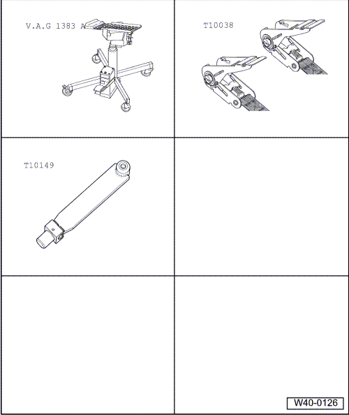
| Special tools and workshop equipment required |
| Engine and gearbox jack -V.A.G 1383 A- |
| Tensioning strap -T10038- |
 Caution
| All bolts on running gear components with bonded
rubber bushes may be tightened only when the component
is in the unladen position (normal position). |
| Bonded rubber bushes can be twisted only to a
limited extent. |
| Axle components with bonded rubber bushes must
therefore be brought to a position equivalent to the
unladen (normal) position before being tightened. |
| Otherwise, the bonded rubber bush would be subject
to torsion loading, shortening its service life. |
|
| To simulate this position on the lifting platform, raise the
axle on one side using the engine and gearbox jack -V.A.G 1383
A- and support -T10149-. |
|
|
|
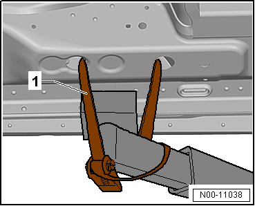
| Before the axle on one side is raised, both sides of the
vehicle must be strapped to the lifting platform arms with
tensioning straps -T10038-. |
| 1 - |
Tensioning strap -T10038- |
 WARNING
| If the vehicle is not strapped down, there is a
danger that the vehicle will slip off the lifting
platform! |
|
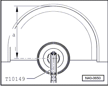
| – |
Turn wheel hub until one of the wheel bolt holes is at the
top. |
| – |
Attach support -T10149- with a wheel bolt. |
|
|
|
| Respective nuts and bolts may be tightened only when
dimension -a- between the centre of
wheel hub and edge of wheel housing has been attained. |
| The dimension -a- depends on
the ride height of the installed running gear: |
|
|
|
| Running gear
1) |
Ride height
-a- in mm |
| Basic
(G01/G02/G07/G18/G22 +2UA) |
385 ± 10 mm |
| Sport (G01/G02 +GM1/
G07+2UC/ G21,G26) |
370 ±
10 mm |
| Raised running gear
(G01/G02 +2UF) |
400 ±
10 mm |
| DCC (G03+2UH/ G03+2UQ) |
375 ±
10 mm |
| GTD (G02+2UC/ G06 + 2UC +
GM03/ G05 + 2UJ + GM03) |
370 ±
10 mm |
| GTI (G06+2UC/ G06 + 2UJ/
G04 + 2UM) |
370 ±
10 mm |
| BlueMotion (G01G02
+2UP+GM1 G07+2UC/ G21/G26) |
370 ±
10 mm |
| GTI Heavy-duty (G06 +
2UN) |
385 ±
10 mm |
| GTE (G20/G23) |
395 ± 10
mm |
| Golf R (G04 + 2UK + QZ0/
G04 + 2UL + QZ0/ G04 +2UK + 1N7/ G04 + 2UL + 1N7) |
365 ± 10
mm |
| Alltrack (G24/ G25) |
398 ±
10 mm |
| Alltrack DCC (G27) |
393 ± 10 mm |
| 1) The type of running gear
fitted to the vehicle is recorded on the vehicle data sticker.
The running gear is identified by the PR number. Allocation of
PR number to corresponding running gear
→ Chapter „Vehicle data sticker“. |
| – |
Raise wheel bearing housing using engine and gearbox jack
until dimension -a- is attained. |
WARNING
| Do not lift or lower the vehicle while the
engine/gearbox jack is under the vehicle. |
| Do not leave engine and gearbox jack under vehicle
longer than necessary. |
|
| – |
Tighten respective nuts and bolts. |
| – |
Lower wheel bearing housing. |
| – |
Pull engine and gearbox jack -V.A.G 1383 A- out from under
vehicle. |
| – |
Remove support -T10149-. |
|
|
|
Special tools and workshop equipment required
Engine and gearbox jack -V.A.G 1383 A-
Tensioning strap -T10038-
Support -T10149-
...
Damage to running gear may go unnoticed during repairs to
load-bearing and suspension parts of accident vehicles. Under
certain circumstances, this undiscovered damag ...
Other materials:
Anti-corrosion wax (in aerosol can)
Designation:
Anti-corrosion wax -D 308 SP5 A1-
Issued 04.2009
Product description
Anti-corrosion wax -D 308 SP5 A1- offers ideal corrosion
protection for areas of the body th ...
Overview - navigation system
The navigation system is available as Discover Media and
Discover Pro version with navigation.
The navigation function is integrated in control unit 1 for
information electronics -J794-.
For Discover Media version, the n ...
Assembly overview - alternator with sliding bushes
1 -
Alternator -C-
Removing and installing
→ Chapter
Checking
→ Chapter
Removing and installing poly V-belt pulley
→ Chapter
Removing and installing voltage reg ...
© 2016-2026 Copyright www.vwgolf.org

 Raising wheel bearing assembly to unladen position (vehicles with coil
springs), front axle
Raising wheel bearing assembly to unladen position (vehicles with coil
springs), front axle Checklist for evaluating running gear on accident vehicles