Volkswagen Golf Service & Repair Manual: Radio
| Layout - radio, Composition Touch and
Composition Colour radio version |
| The radio -R- is installed in the middle of the dash panel. |
| Fault finding is done via Guided fault
finding
→ Vehicle diagnostic tester. |
| For additional information refer to
→ Chapter. |
|
|
|
| Layout - radio, Composition Media radio
version |
| The radio function is integrated in control unit 1 for
information electronics -J794-. |
| Fault finding is done via Guided fault
finding
→ Vehicle diagnostic tester. |
| For additional information refer to
→ Chapter. |
|
|
|
| Layout - radio, Discover Pro radio
version |
| The radio function is integrated in control unit 1 for
information electronics -J794-. |
| Fault finding is done via Guided fault
finding
→ Vehicle diagnostic tester. |
| For additional information refer to
→ Chapter. |
|
|
|
Removing and installing radio -R-, Composition Touch and Composition
Colour version
| Special tools and workshop equipment
required |
|
|
|
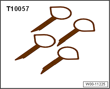
| Radio release tool -T10057- |
| – |
Switch off ignition and all electrical consumers, and remove
ignition key. |
 Caution
| Danger of damage to component surfaces. |
| When using leverage tools, mask visible areas of the
component with commercially available adhesive tape. |
|
| – |
Remove centre dash panel trim
→ General body repairs, interior; Rep. gr.70 |
|
|
|
| – |
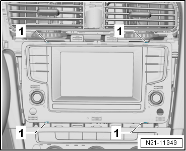
Insert radio release tools -T10057- into slots
-1- in display unit for control
device of front display and information control panel -J685-. |
|
|
|
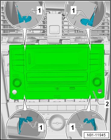
| – |
Release upper locking mechanisms -1-
by pressing them in direction of travel. |
| – |
Release lower locking mechanisms -1-
by pressing them in direction of travel. |
| – |
Release and detach connectors. |
| Install in the reverse order of removal. When doing this,
note the following: |
Caution
| Danger of damage to components. |
| When inserting display unit for control device of
front display and information control panel -J685-
combined with control unit 1 for information electronics
-J794- do not press on the display and the control
elements. |
|
| – |
Slide it radio -R- until it engages. |
|
|
|
| Removing and installing radio -R-,
Composition Media and Discover Media or Discover Pro version |
| The radio is part of the control unit 1 for information
electronics -J794- and is located in the glove box. |
| – |
Removing control unit 1 for information electronics -J794-
→ Chapter. |
|
|
|
Special tools and workshop equipment
required
Torque wrench -V.A.G 1783-
Note
...
© 2016-2026 Copyright www.vwgolf.org

 Removing and installing roof aerial -RX5-
 Telephone system