Volkswagen Golf Service & Repair Manual: Overview of fitting locations
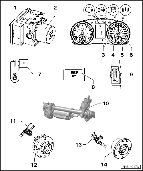
Overview of fitting locations - ABS/ESP
| 1 - |
ABS control unit -J104- |
| Installation location: on hydraulic unit, on passenger side in
engine compartment. |
| Do not separate connector before successfully completing
self-diagnosis. Switch ignition off before separating connector. |
| The following components are integrated into the control unit: |
| Control unit for electromechanical parking brake -J540- |
| Lateral acceleration sender -G200- |
| Longitudinal acceleration sender -G251- (depending on equipment
fitted) |
| The components cannot be renewed individually. |
| Removing and installing
→ Chapter. |
| 2 - |
ABS hydraulic unit -N55- |
| Fitting location: in engine compartment on passenger side |
| The hydraulic unit consists of the components: |
| Brake pressure sender -G201- |
| Valve block (contains inlet and outlet valves). |
| ABS hydraulic pump -V64- and valve block must not be separated from
one another. |
| Removing and installing
→ Chapter. |
| 3 - |
Brake pad warning lamp -K32- |
| Location: in dash panel insert. |
| 4 - |
ABS warning lamp -K47- |
| Location: in dash panel insert. |
| 5 - |
ESP and TCS warning lamp -K155- |
| Location: in dash panel insert. |
| 6 - |
Brake system warning lamp -K118- |
| Location: in dash panel insert. |
| 7 - |
Brake light switch -F- |
| Location: on brake master cylinder. |
| Removing and installing
→ Chapter. |
| 8 - |
TCS and ESP button -E256- |
| Two versions, therefore two fitting locations: |
| Function button in menu of infotainment system |
| Removing and installing TCS and ESP button -E256- in centre console
→ Electrical system; Rep. gr.96. |
| 9 - |
Diagnostic connection |
| Location: Driver footwell cover. |
| 10 - |
Steering angle sender -G85- |
| Fitting location: in steering rack. |
| The steering angle sender -G85- cannot be renewed separately. |
| Removing and installing steering
→ Running gear, axles, steering; Rep. gr.48. |
| 11 - |
Front right/left speed sensor -G45-/-G47- |
| Removing and installing
→ Chapter. |
| 12 - |
Wheel hub with wheel bearing |
| ABS sensor ring is installed in wheel bearing |
| Check ABS sensor ring
→ Chapter |
| 13 - |
Rear right/left speed sensor -G44-/-G46- |
| Removing and installing (front-wheel drive)
→ Chapter |
| 14 - |
Wheel hub with wheel bearing |
| ABS sensor ring is installed in wheel bearing |
| Check ABS sensor ring
→ Chapter |
Repair instructions for repair work on ABS
The ABS brake system is divided diagonally. The
servo-assistance is effected pneumatically by the vacuum brake
servo unit. ...
Other materials:
EU general type approval number, sales type and sales or trade designation
The designations below are only applicable for VW vehicles
Since 1.1.1998, all passenger cars licensed within the European
Union must have a type approval corresponding to EU guidelines. Vehicles
licensed for road use with single-vehicle approval according to § 21
St ...
Removing and installing front trim for sliding sunroof
Special tools and workshop equipment
required
Cartridge gun -V.A.G 1628-
Electric cutter -V.A.G 1561A-
...
Paintwork system for plastic components
Issue 03.2010
This universal system allows simple and reliable painting of
all external plastic components in standard applications.
(Synthetic types: PP, EPDM, ABS, PC, PPO, PBTP, UP-GF, PA, PVC,
R-TPU, PUR). This technical data sheet i ...
© 2016-2026 Copyright www.vwgolf.org

 General information