Volkswagen Golf Owners Manual: Fuse tables for fuses in the engine compartment
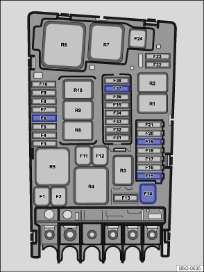
Fig. 231 Engine compartment: fuse layout
 First read and observe the introductory information
and safety warnings
First read and observe the introductory information
and safety warningsThe table shows the fuse locations for the items of electrical equipment which are most relevant to the customer. The left column contains the location, the other columns contain the fuse designs, the amp rating and the consumer.
| Fuse location | Fuse design | Amp rating | Electrical consumers |
|---|---|---|---|
| F6 | ATO® | 5 | Brake light sensor |
| F14 | JCASE® | 40 | Windscreen heating |
| F15 | ATO® | 15 | Horn |
| F19 | ATO® | 30 | Windscreen wipers |
| F37 | ATO® | 20 | Auxiliary heater |

Depending on the version and specification of your vehicle, the fuse numbers and positions may differ to those given in the table. If necessary ask your Volkswagen dealership for the exact fuse layout.
 Fuse table
Fig. 230 In the dash panel: fuse layout
First read and observe the introductory information
and safety warningsThe table shows the fuse locations for the items of electrical
equipment which are ...
 Changing a blown fuse
Fig. 232 Blown fuse: A: flat blade fuse,
B: JCASE® fuse
Fig. 233 Remove or insert fuse with plastic
pliers: A. flat blade fuse, B. JCASE® fuse
First read and observe the introductory informa ...
Other materials:
Balancing wheel, conditions
Before you start balancing the wheels, the following
requirements must be met.
Tyre pressure must be OK.
Tread must not be worn on one side. Tread depth should be at
least 4 mm.
T ...
Checking holding pressure, engine code CWVA
Special tools and workshop equipment required
Pressure tester -VAS 6550-
Removal wedge -3409-
Connector cable -VAS 6550/3-3-
Connector cable -VAS 6550/3-4-
Vehicle diagnostic tester
...
Removing and installing activated charcoal filter
Removing
–
Observe safety instructions
→ Chapter.
–
Observe rules for cleanliness
→ Chapter.
–
Remove rear right wheel
→& ...
