Volkswagen Golf Owners Manual: Fuse table
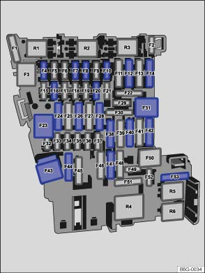
Fig. 230 In the dash panel: fuse layout
 First read and observe the introductory information
and safety warnings
First read and observe the introductory information
and safety warningsThe table shows the fuse locations for the items of electrical equipment which are most relevant to the customer. The left column contains the location, the other columns contain the fuse designs, the amp rating and the consumer.
| Fuse location | Fuse design | Amp rating | Electrical consumers |
|---|---|---|---|
| F4 | MINI® | 7.5 | Infotainment system operating system |
| F7 | MINI® | 10 | Air conditioning system or heating and fresh air system operating unit, relay rear window heating, selector mechanism for the automatic gearbox |
| F8 | MINI® | 10 | Light spindle switch, rain sensor, electronic parking brake |
| F10 | MINI® | 10 | Display |
| F12 | ATO® | 20 | Infotainment services |
| F14 | ATO® | 30 | Blower control |
| F16 | MINI® | 7.5 | Telephone |
| F20 | MINI® | 15 | Seat adjuster |
| F23 | JCASE® | 40 | Exterior lights |
| F24 | ATO® | 30 | Electric panorama sliding/tilting roof |
| F26 | ATO® | 30 | Seat heating |
| F28 | ATO® | 20 | Left trailer controller unit |
| F31 | JCASE® | 40 | Exterior lights |
| F38 | ATO® | 20 | Right trailer controller unit |
| F40 | ATO® | 20 | Cigarette lighter, electrical socket |
| F42 | ATO® | 40 | Windscreen washer, headlight washer system |
| F43 | JCASE® | 30 | Interior lighting |
| F44 | ATO® | 15 | Trailer controller unit |
| F47 | ATO® | 15 | Rear wiper |
| F53 | ATO® | 30 | Rear window heating |

Depending on the version and specification of your vehicle, the fuse numbers and positions may differ to those given in the table. If necessary ask your Volkswagen dealership for the exact fuse layout.
Electric windows and the electrically adjustable seats can be secured via circuit breakers. They switch on automatically a few seconds after the strain, e.g. frozen windows has been relieved.
 Fuses in the vehicle
Fig. 228 Fuse box cover in the dash panel:
A: left-hand drive vehicle, to the left-hand side of the steering wheel B: right-hand
drive vehicle, on the driver side
Fig. 229 In the engine compartm ...
 Fuse tables for fuses in the engine compartment
Fig. 231 Engine compartment: fuse layout
First read and observe the introductory information
and safety warningsThe table shows the fuse locations for the items of electrical
equipment which ar ...
Other materials:
Connection diagram - activated charcoal filter
Note
Fuel tank leak detection takes advantage of the fact that a
vacuum develops naturally in the fuel system as the fuel in the
tank cools. The variables temperature and pressure are necessary
for fuel tank leak detection. The temperature senso ...
Removing and installing mirror cover
Note
Removal and installation are described only for the left mirror
cover. The right side is similar.
Removing
–
Remove mirror glass
→ Chapter.
–
Release locking hook ...
Removing and installing front side window
WARNING
Always wear safety goggles and leather gloves.
Note
To cut out the front side window, use the wire reel -VAS 6452/1-.
–
Pull trim strip (if fitted) out of seal.
Protect surr ...
