
Volkswagen Golf Owners Manual: Electrical controls on the front seats
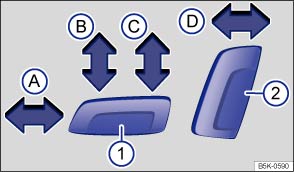
Fig. 44 Moving the front left seat forwards and backwards, adjusting the backrest and the seat cushion for height and tilt
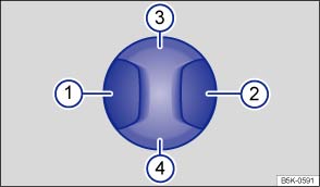
Fig. 45 Adjusting the lumbar support.
 First read and observe the introductory information
and safety warnings
First read and observe the introductory information
and safety warnings The layout of the controls on the front right-hand seat is a mirror image of the layout of the controls on the front left-hand seat.
The seat may have a combination of mechanical and electrical controls.
| Pressing the switch in the direction of the arrow : | ||
|---|---|---|
| ① | Ⓐ | Slides the seat forwards or backwards. |
| Ⓑ | Adjusts the angle of the seat cushion. | |
| Ⓒ | Raises or lowers the seat. | |
| ② | Ⓓ | Adjusts the angle of the backrest. |
| Pressing the switch in the corresponding area : | ||
| ① or ② | Adjusts the curve of the lumbar support. | |
| ③ or ④ | Adjusts the height of the lumbar support. | |
Depending on the vehicle equipment level, it may be possible to assign the seat
position to the vehicle key using the 

 button and the
 and Seats function buttons in the infotainment
system .
and Seats function buttons in the infotainment
system .

 WARNING
- The electrical front seat adjustment also works when the ignition is switched off. Never leave children or people requiring assistance alone in the vehicle.
- In the event of an emergency, stop the electrical adjustment by pressing another switch.

 NOTICE

 Mechanical controls on the front seat
Fig. 43 Front left-hand seat controls
First read and observe the introductory information
and safety warnings The layout of the controls on the front right-hand seat
is a mirror image of the ...
 Adjusting the
head restraints
Adjusting the
head restraints
Fig. 46 Adjusting front head restraint
Fig. 47 Adjusting rear head restraint
First read and observe the introductory information
and safety warnings Every seat is fitted with a head restrain ...
Other materials:
Removing and installing onboard supply control unit -J519-, RHD vehicles
Note
When renewing the control unit, select
Renew function for the respective control unit in
Guided fault finding or
Guided functions mode
→ Vehicle
diagnostic tester.
Removing
â ...
Removing and installing front body acceleration senders -G341-/-G342-
Special tools and workshop equipment
required
Torque wrench -V.A.G 1410-
Removing
–
Pull seal off entire length of plenum chamber cover.
...
Stone chip guard -AKR 311 KD1 10
Designation:
Stone chip guard -AKR 311 KD1 10-, black
Issue 02.2014
Product description
Stone chip guard -AKR 311 KD1 10-, black may be thinned with
water.
...
