Volkswagen Golf Service & Repair Manual: Checking inner constant velocity joint
| The joint is to be dismantled when following work is done: |
| Replacement of grease if very contaminated |
| Check of running surfaces for wear |
|
|
|
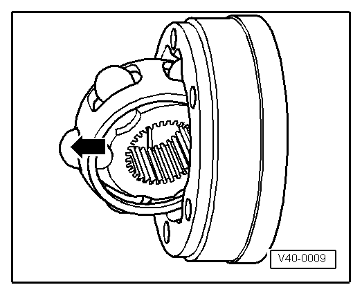
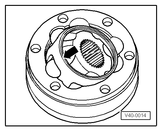
| – |
Swing ball hub and ball cage. |
| – |
Press out joint body in direction of arrow. |
| – |
Press balls out of cage. |
 Note Note
| The ball hub and joint body are paired. Do not interchange
them. |
|
|
|
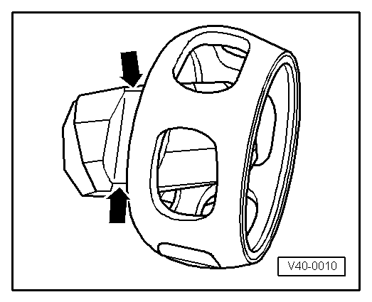
| – |
Tip ball hub out of ball cage via ball track
-arrows-. |
| – |
Check joint body, ball hub, ball cage and balls for pitting
and traces of seizing. |
| Excessive circumferential backlash in the joint is
noticeable during load change jolts. In this case the joint must
be renewed. Smoothing and traces of wear of the balls are no
reason to renew the joint. |
| Install in reverse order of removal, observing the
following: |
|
|
|
| – |
Insert hub into cage via the two chamfers. The hub can be
installed in any position. Press balls into cage. |
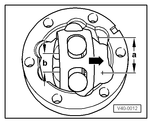
| The ball hub has two different distances between the ball
tracks: a smaller one and a larger one. |
| – |
Insert hub with cage and balls at a right angle to joint
body. |
|
|

|
| When inserting, ensure that the wide spacing
-a- on the joint body is aligned
with the narrow spacing -b- on the
hub after it is swung in. |
| Chamfer on internal diameter of ball hub (splines) must face
large diameter of joint body. |
| – |
Also take note of chamfer on interior diameter of ball hub.
It must be visible after swivelling in. |
|
|
|
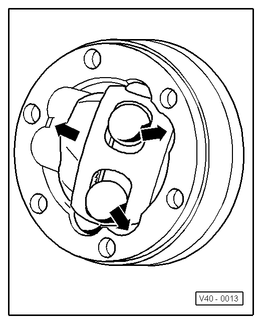
| – |
Swivel the hub into the joint body; at the same time the hub
must be swivelled out of the cage -arrows-
far enough to allow the balls to fit into the ball tracks. |
|
|
|
| – |
Swivel in hub with balls by applying firm pressure to cage
-arrow-. |
| Checking function of constant
velocity joint |
| The constant velocity joint is correctly assembled if the
ball hub can be moved by hand backwards and forwards over its
entire range of axial movement. |
|
|
|
The joint is to be dismantled to renew the grease if it is
heavily soiled, or to check the running surfaces of the balls
for wear and damage.
R ...
Other materials:
Notes to repairs on refrigerant circuit
WARNING
When working on the refrigerant circuit, observe
generally applicable safety rules and the Regulations
for Pressure Tanks.
Caution
...
Infrared heater -VAS 6874
Designation:
Infrared heater -VAS 6874-
Product description:
The infrared heater is used to dry putty, filler, base coat,
top coat and clear coat on vertical surfaces with 2 timers for
flashi ...
2-pack HS clear coat
Designation:
2-pack HS clear coat -L2K 769 500 A5-
Issued 10.2012
Product description
2-pack HS clear coat is a VOC compliant, high-grade
high-solid clear coat.
...
© 2016-2026 Copyright www.vwgolf.org

 Checking outer constant velocity joint