Volkswagen Golf Service & Repair Manual: Assembly overview - fuel tank, vehicles with fuel tank leak detection
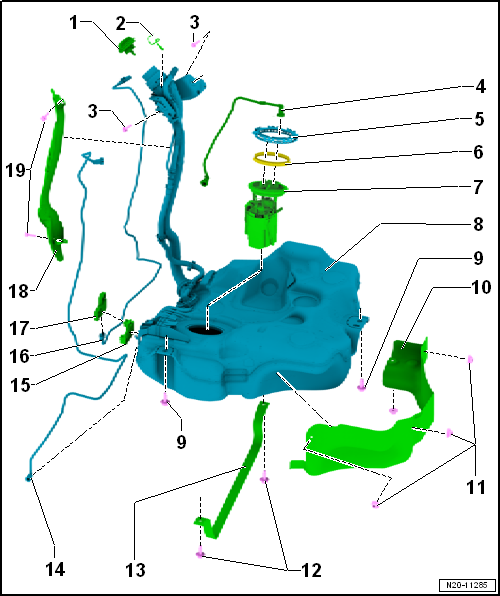
| Screw in until engages audibly |
| Secured to tank flap unit by means of retaining strap. |
| To pull off, press release button on connection. |
| Plug-in connectors must engage »audibly«
when joined. |
| Ensure plug-in connector is secured properly by pulling it. |
| Disconnect plug-in connectors
→ Chapter |
| Assembly overview
→ Chapter. |
| Removing and installing
→ Chapter. |
| With fuel gauge sender -G-. |
| Removing and installing fuel gauge sender -G-
→ Chapter. |
| With fuel system pressurisation pump -G6-. |
| Checking fuel system pressurisation pump -G6-
→ Chapter. |
| Removing and installing
→ Chapter. |
| Mark direction of travel when removing. |
| To activated charcoal filter solenoid valve 1 -N80- |
| For control unit for fuel tank leak detection -J909-. |
| For control unit for fuel tank leak detection -J909-. |
| 17 - |
Control unit for fuel tank leak detection -J909- |
| For securing protective plate |
1 -
Cap
Screw in until engages audibly
Secured to tank flap unit by means of retaining strap.
2 -
Earth connecti ...
1 -
Breather line
To activated charcoal filter
Do not kink
Clipped onto fuel tank
To pull off, press rele ...
Other materials:
Removing and installing operating unit for window regulator in driver door
-E512-
Note
The removal and installation procedures are described for
LHD vehicles. Removal and installation for RHD vehicles are
similar.
Removing
–
Remove front door trim panel
→ ...
Assembly overview - assembly mountings
1 -
Bolt
Renew
Tightening sequence → Fig.
2 -
Engine support
Specified torque and tightening sequence
→ Fig.
3 -
Engine mounting
...
Displays
Fig. 178 In the instrument cluster display:
examples of recognised speed limits or overtaking restrictions with accompanying
additional signs
First read and observe the introductory information
and safety warnings
Traffic sign recognition texts
Cause and solut ...
© 2016-2026 Copyright www.vwgolf.org

 Assembly overview - fuel tank, vehicles with front-wheel drive and torsion
beam rear suspension
Assembly overview - fuel tank, vehicles with front-wheel drive and torsion
beam rear suspension Assembly overview - fuel tank, vehicles with four-wheel drive