Volkswagen Golf Service & Repair Manual: Assembly overview - front brakes
 Note Note
| After every brake pad change, depress brake pedal firmly
several times with vehicle stationary, so that brake pads are
properly seated in their normal operating position. |
| Use the brake filling and bleeding equipment -VAS 5234- to
draw off brake fluid from the brake fluid reservoir. |
| Before removing a brake caliper or disconnecting a brake
hose, fit brake pedal depressor -V.A.G 1869/2- (when doing this,
release pressure in system). |
| Assembly overview - front brakes PC57 and C60: |
|
|
|
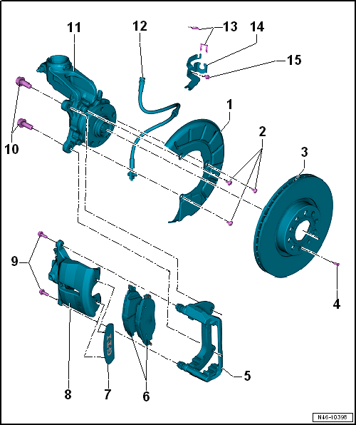
| Always renew on both sides of an axle. |
| Remove brake caliper and brake carrier prior to removing. |
| Apply thin coat of lithium grease G 052150 A2 to brake pad guide
surfaces. |
| Thickness: 14 mm not including backplate. |
| With front right brake pad wear indicator |
| When wear reaches a predetermined limit (approx. 4 mm), the warning
lamp in the dash panel insert comes on. Sensors can be renewed
individually. |
| Wear limit: 2 mm not including backplate. |
| Checking thickness
→ Booklet. |
| Always renew on both sides of an axle. |
| Removing and installing
→ Chapter |
| Allocation
→ Electronic Parts Catalogue (ETKA). |
| Do not disconnect brake hose when changing pads. |
| Removing and installing
→ Chapter |
| Allocation
→ Electronic Parts Catalogue (ETKA). |
| 9 - |
Hexagon bolt (self-locking) |
| 11 - |
Wheel bearing housing |
| With bolted brake carrier. |
| Allocation
→ Electronic Parts Catalogue (ETKA). |
| 12 - |
Brake hose with banjo union and banjo bolt |
| Ensure correct installation position |
Special tools and workshop equipment
required
Torque wrench -V.A.G 1331-
...
Other materials:
Removing and installing belt height adjuster, 2-door model
Removing
–
Press belt height adjuster button and move slider of belt
height adjuster to lowest position.
–
Detach upper B-pillar trim
→ Chapter.
–
...
Introduction
This chapter contains information on the following subjects:
→ Warning lamp
→ Checking the electrolyte level of the vehicle battery
→ Charging, replacing, disconnecting and connecting the vehicle battery
The vehicle battery is a component of the electrical ...
Removing dual clutch
Special tools and workshop equipment required
Hook -3438-
Engine bung set -VAS 6122-
Support device -T10323-
-T10356/5- from assembly tool -T10356-
Puller -T10373-
Thrust piece -T10376- ...
© 2016-2026 Copyright www.vwgolf.org

 Front brakes
 Removing and installing brake pads, front brakes