Volkswagen Golf Service & Repair Manual: Assembly overview - emission control
| Specified torque and tightening sequence
→ Fig. |
| Specified torque and tightening sequence
→ Fig. |
| Specified torque and tightening sequence
→ Fig. |
| Specified torque and tightening sequence
→ Fig. |
| 10 - |
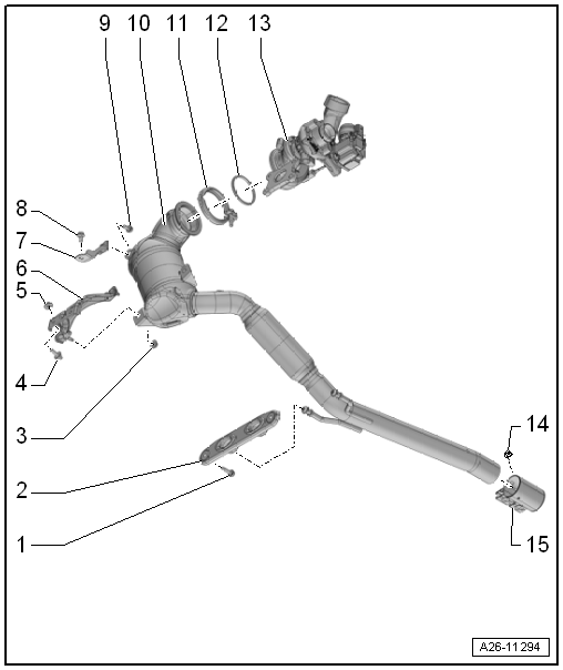
Front exhaust pipe with catalytic converter |
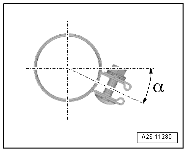
| Do not bend flexible joint more than 10° - otherwise it can be
damaged. |
| Install decoupling element so that it is not under tension. |
| Take care not to damage wire mesh on decoupling element. |
| Protect catalytic converter from damage by knocks and impact |
| Removing and installing
→ Chapter |
| Do not remove protective packaging from replacement part until you
are ready to fit the flexible joint |
| Aligning exhaust system free of tension
→ Chapter |
| Specified torque and tightening sequence
→ Fig. |
| Removing and installing
→ Chapter |
| Align exhaust system free of tension before tightening
→ Chapter. |
| Installation position → Fig. |
| Tighten threaded connections evenly. |
| Installation position of front clamp |
| – |
Fit clamp in position shown. |
| Bolted connection facing towards right |
|
|
|
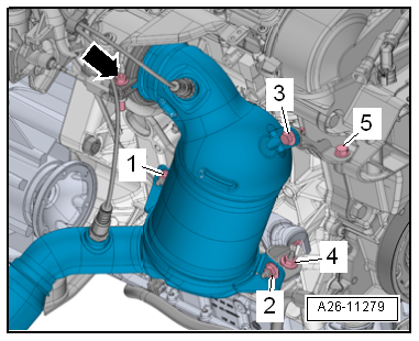
| Installing catalytic converter - tightening torque and
sequence |
|
|
|
| 1) |
| – |
Fit catalytic converter to turbocharger and fit screw-type
clip -arrow- without tightening |
|
|
| 2) |
| – |
Loosely screw in bolts -3, 5-
and bolts -1, 2, 4- by hand |
|
| It should still be possible to move catalytic converter and
bracket. |
|
| 3) |
| – |
Tighten screw-type clip -arrow- |
|
15 Nm |
| 4) |
| – |
Tighten bolts and nuts in the sequence
-1 ... 5- |
|
20 Nm |
Note
The catalytic converter is removed together with the front
exhaust pipe.
Special tools and workshop equipment
required
...
© 2016-2026 Copyright www.vwgolf.org

 Emission control
 Removing and installing catalytic converter