Volkswagen Golf Service & Repair Manual: Assembly overview - brake servo/brake master cylinder, LHD vehicles
| Complete brake master cylinders and brake servos can be renewed
independently of each other. |
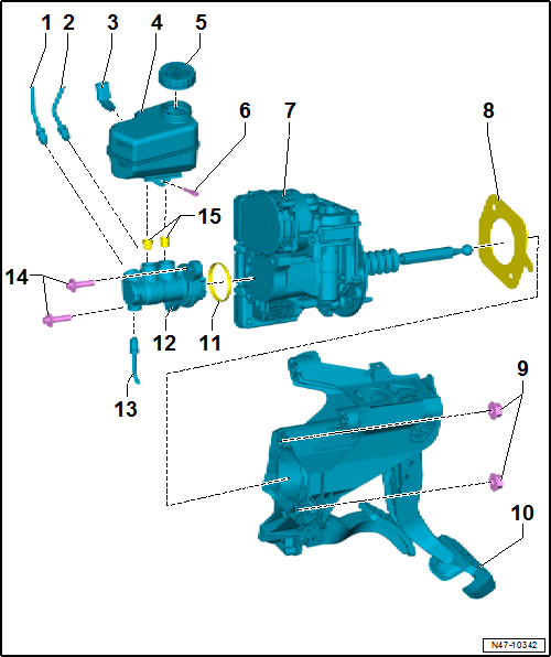
| From secondary piston circuit of brake master cylinder to hydraulic
unit. |
| From primary piston circuit of brake master cylinder to hydraulic
unit. |
| 3 - |
Brake fluid level warning contact -F34- |
| 4 - |
Brake fluid reservoir |
| Removing and installing
→ Chapter |
| The following electrical components are integrated in the brake
servo: |
| Brake pedal position sender -G100- |
| Brake pedal position sender 2 -G836- |
| Voltage supply sender 1 -G730- |
| Voltage supply sender 2 -G731- |
| Brake servo current sensor -G822- |
| Brake servo temperature sender 1 -G838- |
| Brake servo temperature sender 2 -G839- |
| Motor position sender for brake servo -G840- |
| Brake servo control unit -J539- |
| Motor for electromechanical brake servo -V548- |
| Always renew after removing. |
| 10 - |
Mounting bracket with brake pedal |
| 12 - |
Brake master cylinder |
| Cannot be repaired. If faulty, renew as a complete unit. |
| Removing and installing
→ Chapter |
| To brake system pressure accumulator -VX70- |
| Moisten with brake fluid before installing |
Complete brake master cylinders and brake servos can be renewed
independently of each other.
1 -
Mounting bracket with brake pedal
Assembly ...
Other materials:
Assembly overview - tail lights in vehicle body, with LEDs
1 -
Securing element
Specified torque: 2 Nm
2 -
Seal
Self-adhesive
Renew if damaged.
3 -
Left tail light -MX3-/right tail light -MX4-
Tail light in bod ...
Towing a trailer
Fig. 154 ParkPilot screen display when
towing a trailer (colour)
First read and observe the introductory information
and safety warnings Only the scanned area to the front of the vehicle is
shown on the infotainment system screen in vehicles with a factory-fitted towing
bracket and a tra ...
Capacities
First read and observe the introductory information
and safety warnings
Fuel tank capacity
Petrol and diesel engines with front-wheel drive
approx. 50 l,
of which approx. 5 l reserve.
Petrol and diesel engines with fo ...
© 2016-2026 Copyright www.vwgolf.org



 Assembly overview - brake servo/brake master cylinder, RHD vehicles