Volkswagen Golf Service & Repair Manual: Wiring open circuit with two repair positions
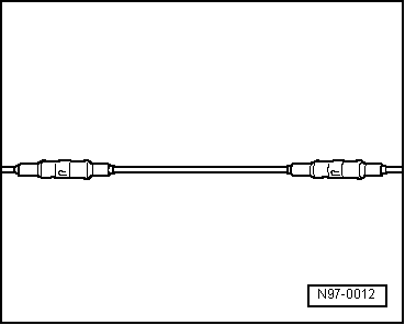
| Repair position with interlinked wire. |
| – |
Place the wire to be repaired to the side at two points
(about 20 cm to both sides of the relevant repair position). |
| – |
If necessary, unbind the wiring harness using the folding
knife. |
|
|
|
| – |
Place the yellow repair wire next to the damage wiring
harness and, using wire strippers -VAS 1978/3-, cut the repair
wire to the required length. |
| – |
Cut the damaged section of wire out of the vehicle's own
single wire. |
|
|
|
| – |
Strip the wire ends of insulation by 6 - 7 mm using the wire
strippers. |
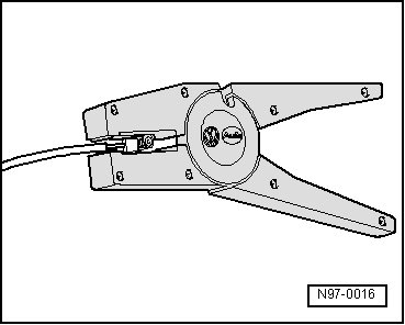
| – |
Push the crimp connector onto one side of the vehicle's own
single wire and on the other side onto the repair wire. |
|
|
|
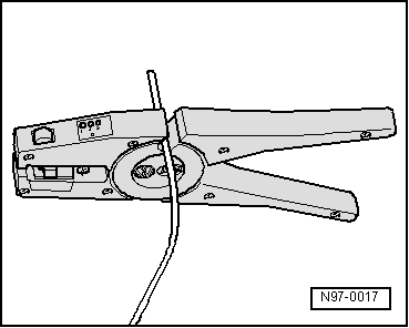
| – |
Crimp the connector using the crimping pliers to both wire
ends. |
| – |
Repeat this procedure on the other end of the repair wire. |
 Note Note
| Ensure without fail that the correct crimp recess is chosen
for the crimp connectors being used
→ Chapter. |
| The insulation on the wires must not be crimped. |
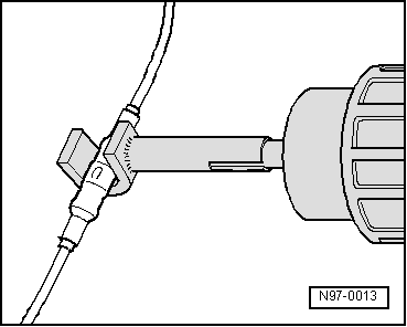
| After crimping, the crimp connector has to be shrink fitted
using the hot air blower in order to prevent any ingress of
moisture. |
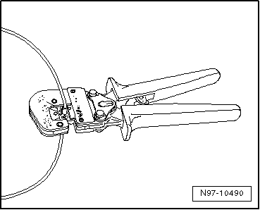
| – |
Place shrink element for hot air blower -VAS 1978/15- on hot
air blower, 220 V / 50 Hz -VAS 1978/14-. |
|
|
|
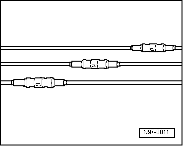
| Ensure that, where several wires have to be repaired, the
crimp connectors are not directly adjacent to each other. To
prevent the circumference of the wiring harness from becoming to
great, position the crimp connectors so they are offset
slightly. |
| If the repair position was already wrapped, this section has
to be wrapped again with yellow insulation tape once the repair
has been carried out. |
| Attach the repaired wiring harness with a cable tie, if
necessary, to prevent it from generating noise when the vehicle
is in motion. |
|
|
|
Repair of optical fibre conductors
| It is very difficult to find the exact location of the
defect. Replace the damaged fibre optic cable by laying a new
cable parallel to the defective fibre optic cable. |
Note
| Via the menu options of the vehicle diagnosis tester “Guided
fault finding” or “Guided functions”, it is possible to
ascertain the components between which the fibre optic cable has
been damaged. |
| The colour “yellow” indicates a fibre optic cable that has
already been repaired. |
| – |
Select “Guided functions” or “Guided fault finding” in the
vehicle diagnosis tester → Vehicle
diagnostic tester. |
| – |
Prepare fibre optic cable
→ Chapter |
 Caution
| Do not excessively bend fibre optic cables. Minimum
radius for bends is 25 mm. |
| Do not route fibre optic cables over sharp edges. |
| Make sure that the ends of fibre optic cables are
not dirty and do not touch them with your bare hands. |
| Do not expose fibre optic cables to heat. |
| It is not permissible to twist 2 fibre optic cables
together or one fibre optic cable with a copper wire. |
| Protect connectors and connecting cables against
dust. Use protective caps from the case. |
|
|
|
|
Repair position with single crimp connector
–
Place the wire to be repaired to one side (about 20 cm
eith ...
Special tools and workshop equipment
required
Fibre optic cable repair kit -VAS 6223A-
...
© 2016-2026 Copyright www.vwgolf.org

 Wiring open circuit with one repair position
 Preparing fibre optic cable