Volkswagen Golf Service & Repair Manual: Removing toothed belt from camshafts, engine code CHPA, CZDA
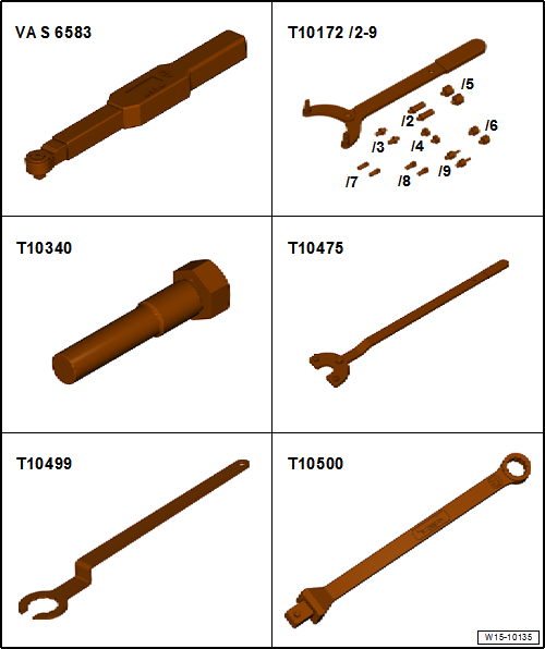
| Special tools and workshop equipment required |
| Counterhold -T10172- with adapter -T10172/1- |
| Special wrench, 30 mm -T10499- |
| Insert tool, 13 mm -T10500- |
| – |
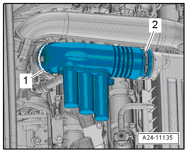
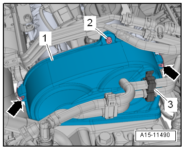
Loosen hose clips -1, 2- and
remove air pipe. |
|
|
|
| – |
Move air hoses clear at air pipe. |
| – |
Detach connector from charge pressure sender -GX26-. |
|
|
|
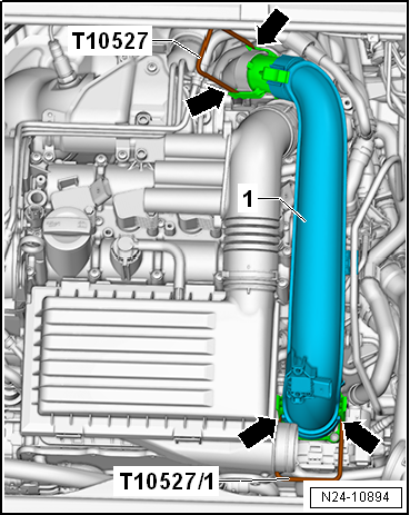
| – |
Release fasteners -arrows-
using release tools -T10527- and -T10527/1-. |
|
|
|
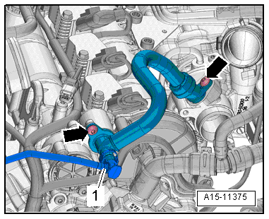
| – |
Press release buttons and pull off hose
-1-. |
| – |
Remove bolts -arrows- and
detach crankcase breather hose. |
| – |
Remove noise insulation
→ General body repairs, exterior; Rep. gr.66. |
| – |
Drain coolant
→ Chapter. |
|
|
|
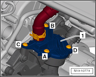
| – |
Unscrew bolts -A ... D-, and
push cover -1- for thermostat to
one side. |
|
|
|
| – |
Lay wiring harness to one side
-arrows-. |
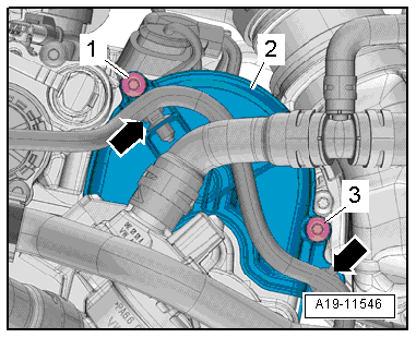
| – |
Unscrew bolts -1, 3- and remove
cover -2- for toothed belt for
coolant pump. |
|
|
|
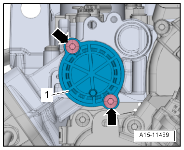
| – |
Unscrew bolts -arrows- and
detach sealing cap -1-. |
| – |
Separate plug-in connectors from fuel hose and from hose to
activated charcoal filter
→ Rep. gr.20. |
| – |
Release hoses from retainer -3-
and lay them to one side. |
|
|
|
| – |
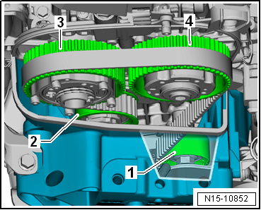
Release clips -arrows- and
detach upper toothed belt guard -1-. |
 Note Note
| Place a cloth under the camshaft adjuster and tensioning
roller to catch the engine oil which runs out. |
| The contact points between the toothed belt and components
such as camshaft pulleys, crankshaft pulley, tensioning roller
and idler pulley must be free of oil. |
|
|
|
| – |
Unscrew bolts -arrows- and
remove cover from camshaft adjuster for exhaust camshaft. |
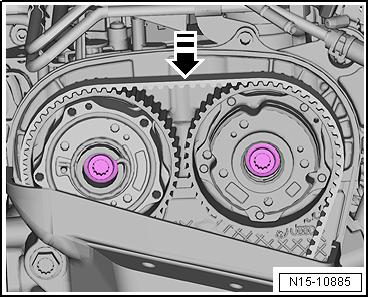
| Rotate crankshaft to “TDC” as follows: |
| – |
Remove ignition coil 1 with output stage -N70- and cylinder
1 spark plug
→ Chapter. |
| – |
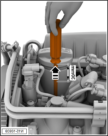
Insert a screwdriver with a shaft length of at least 250 mm
into spark plug hole so that it contact piston crown. |
| – |
Turn the crankshaft in the normal direction of rotation
until the piston in cylinder 1 shows “BDC”. |
|
|
|
| The screwdriver moves in the
-direction of the arrow-. |
|
|

|
| – |
Turn the crankshaft further, until the screwdriver has moved
-30 mm- in the
-direction of the arrows- |
|
|
|
| – |
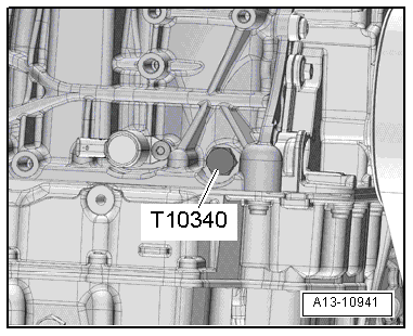
Unscrew plug for “TDC” hole in cylinder block. |
| – |
Screw locking pin -T10340- into cylinder block as far as
stop and tighten to 30 Nm. |
| – |
Rotate crankshaft in normal direction of rotation as far as
stop. |
| The locking pin now rests against the crank web. |
Note
| Locking pin -T10340- locks crankshaft in direction of engine
rotation only. |
| If locking pin -T10340- cannot be screwed in as far as stop,
this indicates that crankshaft is not in the correct position! |
| In this case, proceed as follows: |
| Turn crankshaft 90° in direction of engine rotation. |
| Screw locking pin -T10340- into cylinder block as far as
stop and tighten to 30 Nm. |
| Turn crankshaft in direction of engine rotation as far as
stop. |
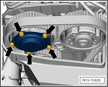
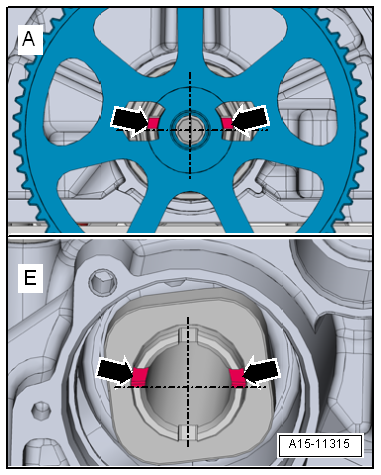
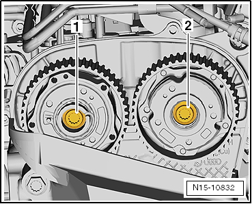
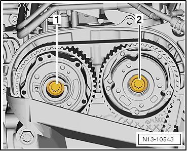
| On both camshafts on gearbox end the asymmetrical grooves
-arrows- must be positioned right
above horizontal camshaft centre line as shown in illustration. |
|
|
|
| The grooves on the exhaust camshaft
-upper arrows- can be accessed through the recesses in
toothed belt pulley for coolant pump. |
| On the inlet camshaft the grooves
-lower arrows- must also be positioned right above
horizontal camshaft centre line. |
| – |
If camshafts are not positioned as described, unscrew
locking pin -T10340-, turn crankshaft one rotation further and
return to “TDC” position. |
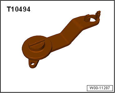
Note
| The camshaft clamp -T10494- must slide into position easily. |
| Do not knock camshaft clamp into place with any kind of
tool. |
| If the camshaft clamp -T10494- does not easily slide into
position: |
|
|
|
| – |
Use assembly tool -T10487- to push against toothed belt in
-direction of arrow-. |
|
|
|
| – |
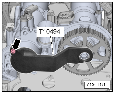
Insert camshaft clamp -T10494- as far as stop into camshaft. |
| – |
Tighten bolt -arrow- by hand. |
|
|
|
| – |
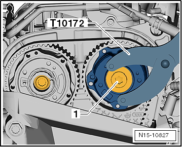
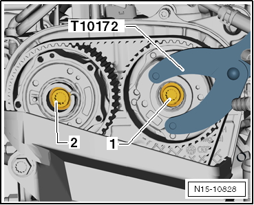
Unscrew plug -1- on camshaft
sprocket on intake side using counterhold -T10172- with adapter
-T10172/1-. |
Risk of damage to camshaft caused by improper handling.Never use the
camshaft clamp for counterholding. |
|
|
| – |
Loosen bolts -1, 2- approx. 1
turn using counterhold -T10172- with adapter -T10172/1-. |
|
|
|
| – |
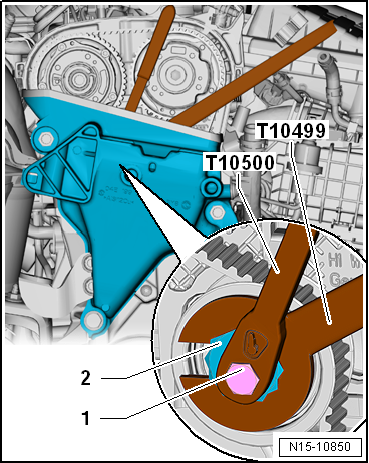
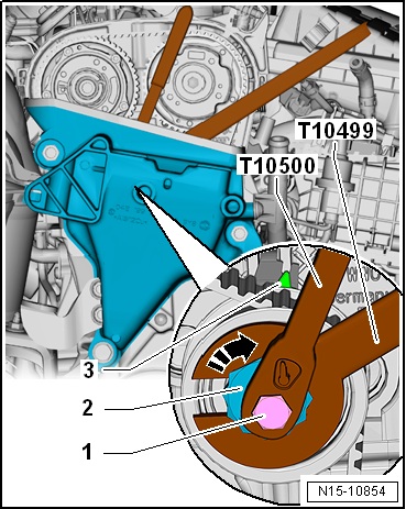
Loosen bolt -1- with tool
insert -T10500-. |
| – |
Release tensioning roller on eccentric adjuster
-2- using special wrench, 30 mm
-T10499-. |
| Risk of damage to the toothed belt. |
| The toothed belt is made of glass fibre fabric. |
| Therefore, bends in the toothed belt must not be smaller
than 50 mm in diameter. |
| Otherwise the service life of the toothed belt will be
reduced. |
| – |
Remove toothed belt from camshaft pulleys. |
| Installing (adjusting valve timing) |
Note
| Renew bolts that are tightened with specified tightening
angle. |
| Renew O-ring of plug if damaged. |
| – |
Check “TDC” position of camshaft and crankshaft: |
|
|
|
| Camshaft clamp -T10494- must be attached to camshaft
housing. |
Risk of damage to camshaft caused by improper handling.Never use the
camshaft clamp for counterholding. |
|
|
| Locking pin -T10340- screwed into cylinder block as far as
stop and tightened to 30 Nm. |
| Crankshaft has been turned in direction of engine rotation
until it rests against locking pin -T10340- = “TDC” position. |
|
|
|
| – |
Renew bolts -1- and
-2- for camshaft pulleys and screw
them in loosely. |
| It should just be possible to turn the adjusters on the
camshafts but no rocking is permissible. |
|
|
|
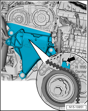
| The sheet-metal tab -arrow- of
the tensioning roller must engage in the cast notch of the
cylinder head. |
| Risk of damage to the toothed belt. |
| The toothed belt is made of glass fibre fabric. |
| Therefore, bends in the toothed belt must not be smaller
than 50 mm in diameter. |
| Otherwise the service life of the toothed belt will be
reduced. |
| Fit toothed belt in prescribed sequence: |
|
|
|
| – |
Pull toothed belt upwards and fit it on idler pulley
-1-, tensioning roller
-2- and camshaft toothed belt
pulleys-3- and
-4-. |
|
|
|
| – |
Tighten bolts -1, 2- initially
to 50 Nm using counterhold -T10172- with adapter -T10172/1-. |
|
|
|
| – |
Unscrew locking pin -T10340-. |
|
|
|
| – |
Remove bolt -arrow- and detach
camshaft clamp -T10494-. |
|
|
|
| – |
Turn crankshaft 2 turns in direction of rotation of engine. |
| – |
Screw locking pin -T10340- into cylinder block as far as
stop and tighten to 30 Nm. |
| – |
Rotate crankshaft further in direction of engine rotation as
far as stop. |
| The locking pin now rests against the crank web. |
Note
| Locking pin -T10340- locks crankshaft in direction of engine
rotation only. |
| – |
It should be possible to insert the camshaft clamp -T10494-
easily. |
| Do not knock camshaft clamp into place with any kind of
tool. |
| If the camshaft clamp -T10494- does not easily slide into
position: |
|
|
|
| – |
Use assembly tool -T10487- to push against toothed belt in
-direction of arrow-. |
|
|
|
| – |
While doing this, insert camshaft clamp -T10494- into
camshafts as far as stop and hand-tighten with bolt
-arrow-. |
| If it is not possible to insert camshaft clamp -T10494-, the
valve timing is not correct. |
| – |
Repeat adjustment of valve timing. |
| If it is possible to insert camshaft clamp -T10494-, the
valve timing is correct. |
|
|
|
| – |
Unscrew locking pin -T10340-. |
|
|
|
| – |
Remove bolt -arrow- and detach
camshaft clamp -T10494-. |
| – |
Tighten bolts -1- and
-2- to final torque setting
→ Chapter. |
|
|
|
| – |
Use counterhold -T10172- with adapter -T10172/1-. |
|
|
|
| – |
Tighten plug -1- using
counterhold -T10172- with adapter -T10172/1-. |
| After completing work, check that locking pin -T10340- and
camshaft clamp -T10504- have been removed. |
| Further assembly is carried out in the reverse order of
removal. |
| → Chapter „Assembly overview - toothed belt“ |
| → Fig. „“Plug for TDC drilling in cylinder block - specified
torque”“ |
| → Chapter „Assembly overview - camshaft housing, engine codes
CHPA, CMBA, CPVA, CXSA, CZCA, CPVB, CZDA“ |
| → Chapter „Assembly overview - crankcase breather system“ |
| → Chapter „Assembly overview - coolant pump, thermostat“ |
| → Chapter „Assembly overview - charge air system“ |
|
|
|
Special tools and workshop equipment
required
Torque wrench -VAS 6583-
...
Special tools and workshop equipment required
Torque wrench -VAS 6583-
Counterhold -T10172- with adapter -T10172/1-
Locking pin -T10340- ...
Other materials:
Using the selection menu in the instrument cluster
Fig. 16 Vehicles without a multifunction
steering wheel: button ① on the windscreen wiper lever for confirming menu points,
and rocker switch ② for changing menus and information displays
Fig. 17 Right-hand side of the multifunction
steering wheel: controls for using the menus and inform ...
Assembly overview - fuel delivery unit/fuel gauge sender, vehicles with
auxiliary heater
1 -
Fuel delivery unit
With fuel system pressurisation pump -G6-.
With integrated fuel filter; fuel filter cannot be renewed
separately
Carrying out electrical test of fuel pump in
Guided fault finding mode → ...
Drawers
Fig. 116 Drawer under the front seat
First read and observe the introductory information
and safety warnings A drawer may be located under each of the front seats
.
Opening or closing the drawer
To open, press the button in the drawer grip and open the drawer.
To close, push the dra ...
© 2016-2026 Copyright www.vwgolf.org

 Checking valve timing, engine codes CHPA, CMBA, CPVA, CXSA, CZCA, CPVB, CZDA
 Removing and installing toothed belt, engine codes CHPA, CZDA