Volkswagen Golf Service & Repair Manual: Removing and installing trailing arm with mounting bracket, except for
e-Golf
| Special tools and workshop equipment
required |
|
|
|
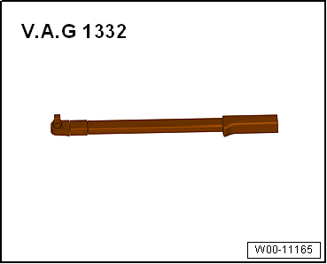
| Torque wrench -V.A.G 1332- |
|
|
|
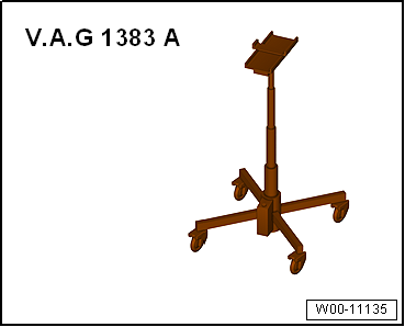
| Engine and gearbox jack -V.A.G 1383 A- |
| – |
Remove spring
→ Chapter. |
|
|
|
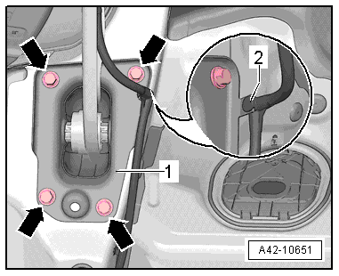
| – |
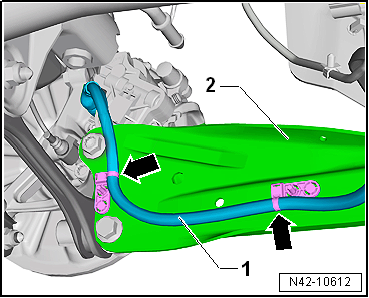
Detach line -1- from trailing
arm -2-. To do this push out inner
pin of retainer -arrows-. |
|
|
|
| – |
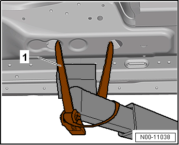
Use tensioning straps -T10038--1-
to strap vehicle to support beams of lifting platform on both
sides. |
 WARNING
| If the vehicle is not strapped down, there is a
great danger that the vehicle will slip off the lifting
platform! |
|
| – |
Position engine and gearbox jack -V.A.G 1383 A--1-
under track rod and press upwards slightly. |
|
|
|
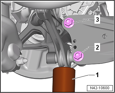
| – |
Unscrew bolts -2- and
-3- one after the other. |
| – |
Remove engine and gearbox jack -V.A.G 1383 A--1-
from under track rod. |
|
|
|
| – |
Detach wire -2- from mounting
bracket -1-. |
| – |
Mark installation position of mounting bracket
-1- on body. |
| – |
Remove trailing arm with mounting bracket. |
| Install in reverse order of removal, observing the
following: |
|
|
|
| – |
Tighten bolts -arrows- onto old
impression marks or previously applied marks. |
| – |
Secure line -2- on mounting
bracket -1-. |
|
|
|
| – |
Position engine and gearbox jack -V.A.G 1383 A--1-
under track rod and press upwards slightly. |
| – |
Screw in bolts -2- and
-3- by hand. |
| – |
Remove engine and gearbox jack -V.A.G 1383 A--1-
from under track rod. |
|
|
|
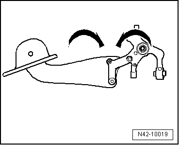
| Do not tighten bolts securing trailing arm to wheel bearing
housing until all other suspension components (especially spring
and shock absorber) on that side are fitted. To tighten, wheel
suspension must be in extended position. Only then do trailing
arm and wheel bearing housing move to the necessary position
-arrows-. |
| – |
Installing spring
→ Chapter. |
|
|
|
| – |
Tighten bolts -2- and
-3-. |
|
|
|
| – |
Install retainers -arrows- on
trailing arm -2- for line
-1-. To do this push in inner pin
of rivets. |
| After installation, wheel alignment must be checked on wheel
alignment unit
→ Chapter. |
| → Chapter „Assembly overview - trailing arm“ |
| → Chapter „Torque settings for wheel bolts“ |
|
|
|
Special tools and workshop equipment required
Assembly tool -3301-
Viscous fan fitting tool -3367-
Carrier -3390-
Torqu ...
Special tools and workshop equipment required
Tube for wheel bearing -3345-
Assembly tool -3346-
Thrust plate -VW 402-
...
Other materials:
Indicator lamp
First read and observe the introductory information
and safety warnings
Lit up
Possible cause
Solution
Engine management system fault (Electronic Power Control).
The engine should be checked by a qualified workshop
as s ...
Checking oil pressure
Special tools and workshop equipment
required
Oil pressure tester -V.A.G 1342-
Procedure
Oil level OK: checking
→ Booklet.
...
Assembly overview - front brakes
Note
After every brake pad change, depress brake pedal firmly
several times with vehicle stationary, so that brake pads are
properly seated in their normal operating position.
Use the brake filling and bleeding equip ...
© 2016-2026 Copyright www.vwgolf.org

 Renewing bonded rubber bush for wheel bearing housing, four-wheel drive
 Repairing trailing arm