Volkswagen Golf Service & Repair Manual: Removing and installing metering pump -V54-, Golf GTE
 Note Note
| Pay attention to correct part number of metering pump -V54-
(different versions)
→ Electronic Parts Catalogue. |
| Checking metering pump -V54- with “end sealing valve”
→ Chapter |
| – |
Observe safety precautions for working on fuel supply system
→ Rep. gr.00. |
| – |
Observe the rules for cleanliness when doing all work on the
fuel supply system
→ Chapter. |
| – |
Always observe the safety precautions when working on the
fuel supply system
→ Chapter. |
| – |
Switch off electrical consumers. |
| – |
Switch off auxiliary/supplementary heater and switch off
ignition. |
The fuel system is pressurised.Danger of injury through fuel
spray.Always wear safety goggles.Always wear safety gloves.To release
pressure, wrap a clean cloth around the connection and carefully loosen
the connection.
Note
|
|
|
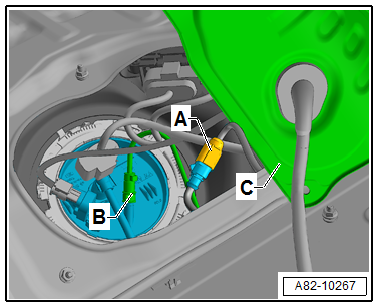
| If there are customer complaints concerning the auxiliary
heater operation in vehicles with a high-voltage system and
problems with the fuel supply of the auxiliary heater are the
cause, detach the cover for the flange -C-
from vehicle prior to removing the fuel tank
→ Rep. gr.20, and check connector
-A- as well as fuel line
-B- leading to metering pump -V54-
for correct installation and damage. |
|
|
|
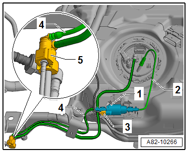
| On vehicles with high-voltage system, the metering pump
-V54--1- cannot be accessed if the
fuel tank is installed
→ Rep. gr.20 (Assembly overview - fuel delivery
unit/fuel gauge sender). Therefore, bleed fuel line
-2- (and corresponding riser tube)
leading to metering pump -V54--1-
as necessary after the fuel tank has been installed (e.g. upon
repair work on the fuel delivery unit, when the fuel line
-2- leading to -V54--1-
has been emptied)
→ Chapter. |
| – |
Remove fuel tank
→ Rep. gr.20. |
|
|
|
| Install metering pump -V54--1-
with correct orientation. The fuel line leading to auxiliary
heater -3- must be connected to the
connection on the same side where the connector
-4- is located. The fuel line
-2- leads to the fuel tank via the
fuel delivery unit (this illustration shows the configuration
for vehicles with high-voltage system). |
|
|
|
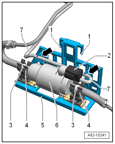
| Install metering pump -V54--6-
with correct orientation. The fuel line leading to auxiliary
heater must be connected to the connection on the same side
where the connector -2- is located
(this illustration shows the configuration for vehicles with
high-voltage system). |
|
|
|
| – |
Renew bracket if retaining tabs -1-
and -5- are damaged or broken off. |
| – |
Insert metering pump -V54--6-
into bracket so that O-type clips -8-
are seated in guides -5- and
connector -2- does not make contact
with bracket. |
| – |
Engage electrical wire -3- in
guides -arrows-. |
| – |
Install bracket with metering pump -V54--6-
ensuring proper engagement of retaining tabs
-1-. |
| – |
Check that fuel lines are properly secured in retainers
-5-. |
| Before installing the fuel tank: |
|
|
|
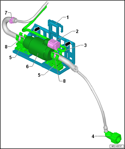
| Make sure that electrical wires and fuel lines (e.g. fuel
lines -2- and
-4- leading to auxiliary heater) are properly routed and
that they are firmly seated in the corresponding retainers. |
| Make sure that the connector on the metering pump -V54- has
properly engaged. |
| Check connection -5- on fuel
line -4- for soiling or damage. |
Note
| If fuel lines make contact with body, they can transfer
sound. |
| – |
Check that fuel lines are correctly seated and routed; fuel
lines must not make contact with body (risk of transferring
sound). |
| → Chapter „Overview of fitting locations - fuel supply system“ |
| Fuel tank; Removing and installing fuel tank
→ Rep. gr.20 |
|
|
|
Note
Pay attention to correct part number of metering pump -V54-
(different versions)
→ Electronic Parts Catalogue.
R ...
–
If you are uncertain as to whether the metering pump -V54--C-
has an end sealing valve or not, connect e.g. hand vacuum pump
-VAS 6213- to connection ...
Other materials:
Removing and installing oil pressure switch -F1-
Special tools and workshop equipment
required
Jointed wrench 24 mm -T40175-
Removing
Note
Fit all heat insulation sleeves in the original posi ...
Remote control
Fig. 185 Auxiliary heater: remote control
Fig. 186 Auxiliary heater: battery cover
for the remote control
First read and observe the introductory information
and safety warnings
Meaning
Switches on the auxiliary heater.
...
Assembly overview - rear wheel housing liner
Note
Minor differences may be encountered in respect of front wheel
housing liner, depending on vehicle model.
Only the left side is shown. The right side is similar.
1 -
Rear wheel housing liner
Materi ...
© 2016-2026 Copyright www.vwgolf.org



 Removing and installing metering pump -V54-, Golf and Golf Estate
 Checking metering pump -V54- with end sealing valve