Volkswagen Golf Service & Repair Manual: Removing and installing knee airbag with driver side knee airbag igniter
-N295-
 WARNING
-
|
|
Observe safety instructions for
pyrotechnic components → Chapter. |
-
|
|
Observe disposal regulations for
pyrotechnic components → Chapter. |
-
|
|
Note allocation of airbag unit to dash
panel → Electronic Parts Catalogue. |
|
|
|
|
| – |
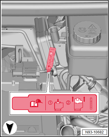
For “e-Golfs” or “Golf GTEs”, disconnect the maintenance
connector for high-voltage system -TW-. |
| – |
Disconnect battery earth cable with ignition switched on
→ Electrical system; Rep. gr.27. |
|
|
|
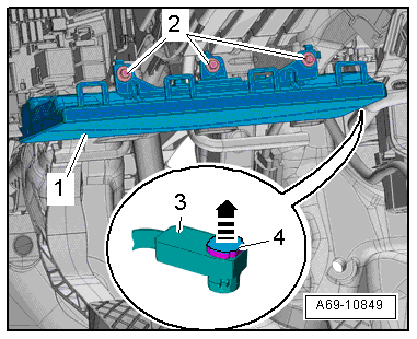
1 -
Knee airbag with driver side knee airbag igniter -N295-.
Removing and installing
→ Chapter
Cau ...
Other materials:
Renewing needle bearing in crankshaft
Only vehicles with a dual clutch gearbox
Special tools and workshop equipment
required
Adapter Kukko -22/1-
...
Removing and installing window regulator
Special tools and workshop equipment
required
Note
Removal and installation are described only for the left
window regulator. Removal and installation of the ...
HS spot thinner
Designation:
HS spot thinner -LVM 006 000 A2-
Issued 06.2013
Product description
HS spot thinner -LVM 006 000 A2- is a special drying
accelerator for small repairs with 2-pac ...
© 2016-2026 Copyright www.vwgolf.org

 Note
Note Caution
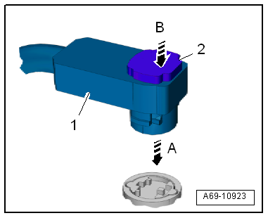
 Assembly overview - knee airbag