Volkswagen Golf Service & Repair Manual: Removing and installing door lock
| Special tools and workshop equipment
required |
|
|
|
| |
|
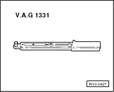
Torque wrench -V.A.G 1331- |
 Note Note
| |
Removal and installation are described only for the left
door lock. The right side is similar. |
| |
The door window must be closed for subsequent work. |
|
|
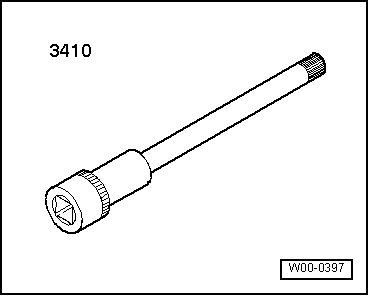
|
| – |
Remove rear door trim
→ General body repairs, interior; Rep. gr.70. |
| – |
Remove inner door cover
→ Chapter. |
| – |
If fitted, disconnect connector. |
| – |
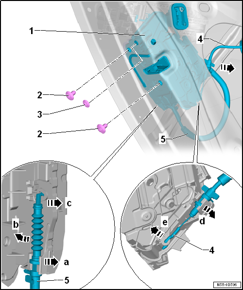
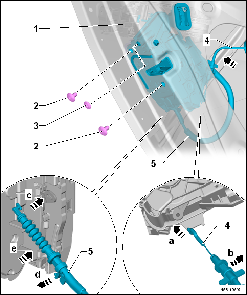
Remove door lock -1- from door
-arrow-. |
Note
| Cables can be detached if this is necessary for subsequent work. |
| Detach cable from mounting bracket |
| – |
Turn cable -5- 90° and take out of
holder -arrow a-. |
| – |
Swivel cable -arrow b- so far until
cable can be threaded out of eye in door lock
-1--arrow c-. |
| Detach cable from interior door handle |
| – |
Turn cable -4- by 90° and take it out
of holding device. |
| – |
Swivel cable -arrow d- so far until
cable can be threaded out of eye in door lock
-1--arrow e-. |
| – |
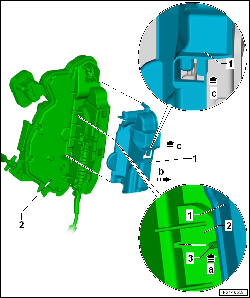
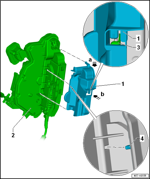
Disengage hook -3- in
-direction of arrow a-. |
| – |
Use the hook to pull cover -1- out of
door lock -2--arrow b-. |
| – |
Pull cover -1- upwards
-arrow c- from door lock
-2-. |
| – |
Attach cables -4- and
-5- to door lock -1-. |
| – |
Insert door lock -1- into door
-arrow f-. |
| – |
If fitted, connect connector. |
| Further installation is performed in the reverse order of removal. |
| l |
It is essential to perform a functional check. If the cables are not
adjusted correctly and the door is closed without having performed a
functional check, the door lock might not unlock and the door can't be
opened. |
| |
→ Chapter „Assembly overview - door handle and door lock“ |
| – |
Push cover -1- onto retainer
-3- on door lock
-2--arrow a-. |
| – |
Engage hook -4- with door lock
-2--arrow b-. |
Special tools and workshop equipment
required
Note
Removal and installation are described only ...
Note
The removal and installation sequence is only for the
left window channel. Removal and installation of the right
windo ...
Other materials:
Assembly overview - speed sensor on front axle
1 -
ABS speed sensor
Clean inside surface of hole before inserting sensor
Coat inside surface with high-temperature paste -G 052 112 A3-
Removing and installing
→ Chapter
2 -
Bolt
...
Indicator lamps and fuel gauge
Fig. 187 In the instrument cluster: fuel
gauge for petrol and diesel
First read and observe the introductory information
and safety warnings
Lit up
Needle position
Possible cause
Solution
Red mark ...
Introduction
This chapter contains information on the following subjects:
→ Petrol
→ Diesel
→ Bioethanol (Ethylalcohol)
Different engines require different fuels. The factory-fitted sticker on the
inside of the tank flap indicates the fuel type that is required for your ...
© 2016-2026 Copyright www.vwgolf.org


 Removing and installing mounting bracket
 Removing and installing window channel