Volkswagen Golf Service & Repair Manual: Removing and installing coolant pump
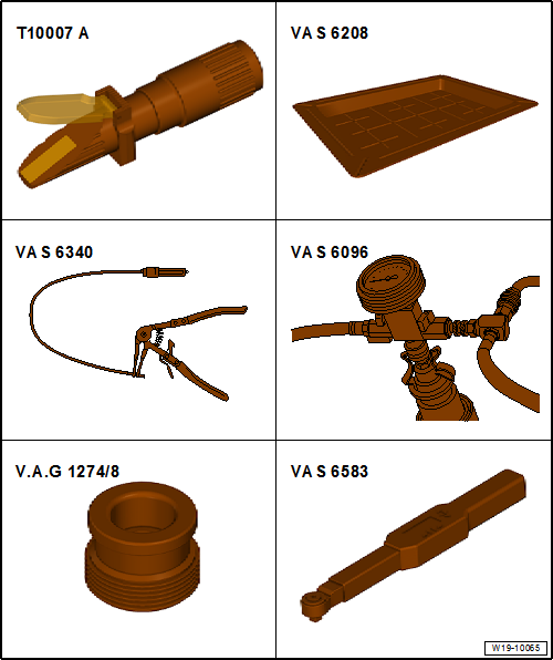
| Special tools and workshop equipment required |
| Drip tray for workshop hoist -VAS 6208- |
| Hose clip pliers -VAS 6340- |
| Cooling system charge unit -VAS 6096- |
| Adapter for cooling system tester -V.A.G 1274/8- |
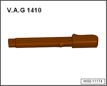
| Torque wrench -V.A.G 1410- |
| – |
Drain coolant
→ Chapter. |
| – |
Remove battery tray
→ Electrical system; Rep. gr.27. |
|
|
|
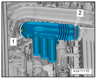
| – |
Loosen hose clips -1, 2- and
remove air pipe. |
| – |
Move air hoses clear at air pipe. |
| – |
Detach connector from charge pressure sender -GX26-. |
|
|
|
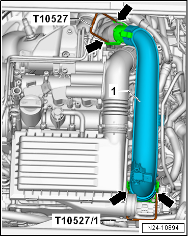
| – |
Release fasteners -arrows-
using release tools -T10527- and -T10527/1-. |
|
|
|
| – |
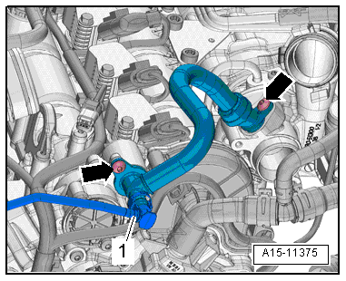
Press release tabs and disconnect hose
-1- for activated charcoal filter. |
| – |
Remove bolts -arrows- and
detach crankcase breather hose. |
|
|
|
| – |
Lay wiring harness to one side
-arrows-. |
| – |
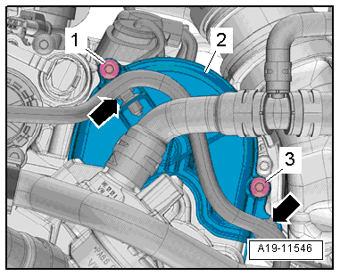
Unscrew bolts -1, 3- and remove
cover -2- for toothed belt for
coolant pump. |
|
|
|
| – |
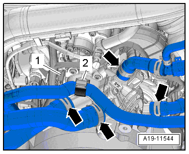
Move clear electrical wiring harness
-1- and coolant hose -2-. |
| – |
Release hose clips -arrows-,
and disconnect all coolant hoses from coolant pump. |
|
|
|
| – |
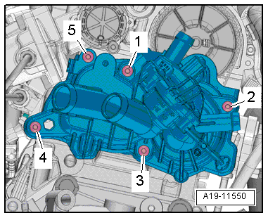
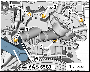
Loosen and unscrew bolts in the sequence
-5 … 1-. |
| – |
Detach coolant pump with toothed belt. |
| – |
Remove thermostat housing if coolant pump is being renewed
→ Chapter. |
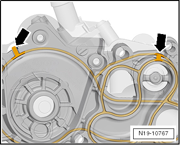
 Note Note
| Renew gasket for housing -arrows-. |
| Renew the toothed belt of the coolant pump. |
| Secure hose connections with hose clips meeting production
standard
→ Electronic Parts Catalogue. |
|
|
|
| – |
Ensure proper seating of gaskets
-arrows-. |
| – |
Lubricate seal for coolant pump lightly with coolant. |
Note
| Always adhere to the sequence of work steps given below when
installing the coolant pump. |
| This ensures that the toothed belt is correctly tensioned. |
| The following work steps must be carried out with the aid of
a 2nd mechanic. |
| – |
Set No. 1 cylinder to TDC
→ Chapter. |
| – |
Fit toothed belt so that it is centred and move coolant pump
into installation position. |
| – |
Mount coolant pump on cylinder head with securing bolts. |
|
|
|
| – |
Pre-tighten bolts in the specified sequence: |
|
|
|
| Stage |
Bolts |
Specified torque |
| 1 |
-1 … 5- |
Screw in to contact by hand |
| 2 |
-1 … 5- |
10 Nm |
| – |
Loosen all bolts again by one turn. |
|
|
|
| Stage |
Bolts |
Specified torque |
| 3 |
-2, 1, 5- |
10 Nm |
| 4 |
-3, 4, 5, 1, 2- |
12 Nm |
| Further installation steps are carried out in the reverse
order; note the following: |
| Coolant hose schematic diagram
→ Chapter. |
| – |
Replenish coolant
→ Anchor. |
| Tightening sequence for coolant pump
→ Anchor |
| → Chapter „Assembly overview - coolant pump, thermostat“ |
| → Chapter „Assembly overview - turbocharger“ |
| → Chapter „Assembly overview - charge air system“ |
| → Electrical system; Rep. gr.27 |
|
|
|
1 -
O-ring
Renew
2 -
Radiator outlet coolant temperature sender -G83-
Removing and installing
→ C ...
Special tools and workshop equipment
required
Counterhold -T10172- with adapter -T10172/2-
...
Other materials:
Interior monitoring system and anti-tow alarm
Fig. 32 Next to the driver seat: button
for switching off the interior monitoring system and anti-tow alarm
Fig. 33 In the roof console: sensors for
the interior monitoring system
First read and observe the introductory information
and safety warnings The interior monitoring system will ...
Introduction
This chapter contains information on the following subjects:
→ The dangers of assuming an incorrect sitting position
→ Correct sitting position
→ Mechanical controls on the front seat
→ Electrical controls on the front seats
→ Adjusting ...
Checking inner constant velocity joint
Removing
The joint is to be dismantled when following work is done:
Replacement of grease if very contaminated
Check of running surfaces for wear
Check of balls for wea ...
© 2016-2026 Copyright www.vwgolf.org

 Assembly overview - coolant temperature sender
 Removing and installing toothed belt pulley for coolant pump, engine codes
CHPA, CMBA, CPVA, CXSA, CZDA, CZCA, CPVB
Removing and installing toothed belt pulley for coolant pump, engine codes
CHPA, CMBA, CPVA, CXSA, CZDA, CZCA, CPVB