Volkswagen Golf Service & Repair Manual: Removing and installing control unit and hydraulic unit, LHD vehicles,
four-wheel drive, »R«
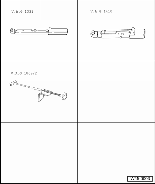
| Special tools and workshop equipment required |
| Torque wrench -V.A.G 1331- |
| Torque wrench -V.A.G 1410- |
| Brake pedal depressor -V.A.G 1869/2- |
| Sealing plugs, assembly part no. 5Q0 698 311 |
|
|
|
| The control unit is bolted to the hydraulic unit and is
located on right in the engine compartment. |
Risk of damage to brake lines if bent.Never excessively bend the brake
lines in the area of the hydraulic unit.
| – |
Read out and note the existing control unit code. |
| – |
If vehicle has a coded radio, note radio code or, if
necessary, request it. |
| – |
Disconnect battery
→ Electrical system; Rep. gr.27 |
|
|
|
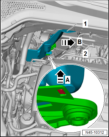
| – |
Remove heat shield -1- from
mounting bracket -2-. To do this,
release catches in -direction of arrow A-,
and remove heat shield in -direction of
arrow B-. |
|
|
|
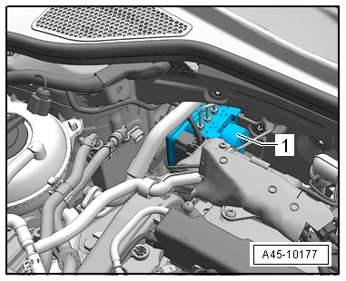
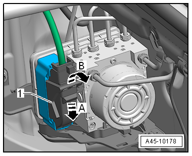
| – |
Press locking slide downwards in
-direction of arrow A-. |
| – |
Release connector -1- in
-direction of arrow B-, and pull it
off control unit. |
|
|
|
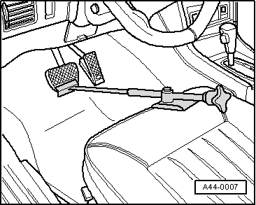
| – |
Apply brake pedal depressor -V.A.G 1869/2-. |
|
|
|
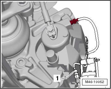
| – |
Connect bleed bottle bleed hose -1-
to bleed valve of front left brake caliper. |
|
|
|
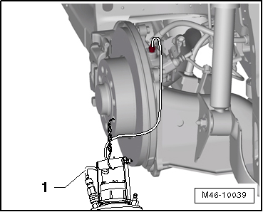
| – |
Connect bleed hose of bleed bottle -1-
to bleed valve of rear left brake caliper. |
| – |
Depress brake pedal at least 60 mm using brake pedal
depressor -V.A.G 1869/2-. |
| – |
Close front left and rear left bleeder valves. |
| – |
Do not remove brake pedal depressor -V.A.G 1869/2-. |
| – |
Place sufficient lint-free cloths under the control unit and
hydraulic unit. |
 Note Note
| Ensure no brake fluid gets onto the contacts of the control
unit and the connector. |
| – |
First identify both brake lines from brake master cylinder
and unscrew from hydraulic unit. |
| – |
Seal threaded holes immediately using sealing plugs from the
assembly part kit with part no. 5Q0 698 311. |
| – |
Mark, unscrew and seal threaded holes of remaining brake
lines (brake calipers). |
|
|
|
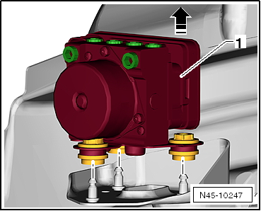
| – |
Pull ABS hydraulic unit -N55- with mounting bracket
-1- upwards in
-direction of arrow- off retainer. |
| – |
Remove ABS hydraulic unit -N55- with mounting bracket
-1- upwards from vehicle. |
| Install in reverse order of removal, observing the
following: |
Note
| Remove sealing plugs from new hydraulic unit only when the
corresponding brake line is to be fitted. |
| If sealing plugs are removed too early from the hydraulic
unit, brake fluid can escape, and it can then no longer be
guaranteed that the unit can be sufficiently filled and bled. |
| When installing the hydraulic unit, ensure that the rubber
dampers are not pressed out of bracket. |
|
|
|
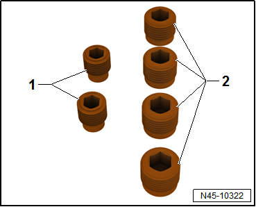
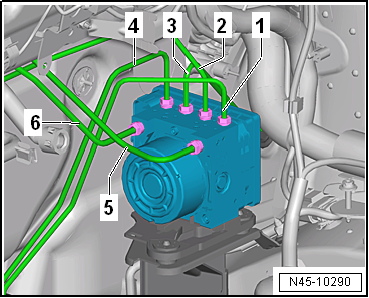
| Tightening sequence of brake lines: |
| – |
Start brake line union screws in sequence
-1- through
-6-. |
| – |
Tighten break line union screws in sequence
-1- through
-6-. |
| – |
Remove brake pedal depressor -V.A.G 1869/2-. |
| – |
Bleed brake system
→ Chapter. |
| – |
Code control unit -J104- with → Vehicle
diagnostic tester in "Guided Fault Finding" mode. |
| To do this, carry out basic setting of the steering angle
sender -G85-, the lateral acceleration sender -G200-, the
longitudinal acceleration sender -G251- and the brake pressure
sender -G201-. |
| → Chapter „Assembly overview - control unit and hydraulic unit,
LHD vehicles“ |
| Connect battery
→ Electrical system; Rep. gr.27. |
| Front bleed valves
→ Chapter „Assembly overview - front brake caliper“ |
| Rear bleed valves
→ Chapter „Assembly overview - rear brake caliper“ |
|
|
 |
Special tools and workshop equipment required
Torque wrench -V.A.G 1331-
Torque wrench -V.A.G 1410-
Brake pedal depressor -V.A.G 1869/2- ...
Special tools and workshop equipment required
Torque wrench -V.A.G 1331-
Torque wrench -V.A.G 1410-
Brake pedal depressor -V.A.G 1869/2- ...
Other materials:
Cleaner for plastics
Designation:
Cleaner for plastics -D 195 850 A1-
Issued 04.2009
Product description
The cleaner for plastics -D 195 850 A1- is a liquid
universal cleaner and thinner/reducer ...
Removing and installing tail light
Note
Removal and installation are described for the left side.
Removal and installation on the right side are carried out in
the same way.
If the event of a defective LED, the entire tail light needs
to be rene ...
Removing and installing brake pedal
It is not possible to remove the brake pedal separately.
–
To be able to remove it, pedal cluster with mounting bracket
must be removed first
→ Chapter.
Note
Removing brake pedal w ...
© 2016-2024 Copyright www.vwgolf.org

 Removing and installing control unit and hydraulic unit, LHD vehicles,
four-wheel drive, diesel engine
Removing and installing control unit and hydraulic unit, LHD vehicles,
four-wheel drive, diesel engine Removing and installing control unit and hydraulic unit, RHD vehicles