Volkswagen Golf Service & Repair Manual: Removing and installing auxiliary heater
| Special tools and workshop equipment
required |
|
|
|
| Torque wrench -V.A.G 1410- (4…20 Nm) |
|
|
|
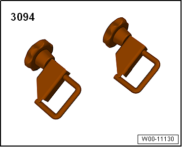
| Hose clamps, up to 25 mm -3094- |
|
|
|
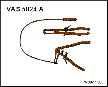
| Pliers for spring-type clips -VAS 5024A- |
|
|
|
| Drip tray for workshop hoist -VAS 6208- |
| Vehicle diagnostic tester |
 Note Note
| There is an identification plate attached to the auxiliary
heater. This identification plate indicates which heater version
is installed in the vehicle:
→ Chapter |
| Coolant circuit must be bled after it is opened
→ Rep. gr.19. |
| Cooling system is pressurized when engine is warm. If
necessary, release pressure and reduce temperature before
carrying out repairs. |
| After the auxiliary heater has been disconnected, it must be
secured to the vehicle body with welding wire. This prevents
damage to the coolant hoses. |
| If the auxiliary heater is to be renewed, first connect the
vehicle diagnostic tester and start the “Renew heater” function
under "Guided Functions". |
| Before beginning repair work, perform the following steps: |
| – |
Connect vehicle diagnostic tester, and select the function
“Renew heater unit” in “Guided fault finding” or “Guided
functions” mode. |
Note
| If possible, certain settings and adaption values for the
auxiliary heater that is to be renewed are read out and stored
via this function. The stored values can then be imported again
to be used for the new auxiliary heater; vehicle diagnostic
tester in “Guided fault finding” or “Guided functions” mode. |
| – |
Switch off electrical consumers. |
Note
| Fit all cable ties and other fasteners for wiring harness at
the same places from which they were detached or cut during
removal of the auxiliary heater. |
| – |
Remove front noise insulation
→ General body repairs, exterior; Rep. gr.66. |
| – |
Detach front right wheel housing liner and remove front
section
→ General body repairs, exterior; Rep. gr.66. |
Danger of severe burns from hot exhaust system. Burns to hands and other
body parts possible.Allow exhaust system to cool.
| – |
Remove exhaust system of auxiliary heater
→ Chapter. |
| – |
Place drip tray underneath vehicle. |
When the engine is warm, the cooling system is under pressure. Danger of
scalding due to steam and hot coolant. There is a risk of injury to the
skin and parts of the body due to scalding.Always wear safety
gloves.Always wear safety goggles.Proceed as follows to release the
pressure: cover the cap of the coolant expansion tank with a cloth, and
open it carefully.
| Further safety precautions for working on the cooling system
→ Rep. gr.00. |
|
|
|
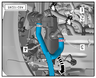
| – |
Clamp off coolant hoses with hose clamps, up to Ш 25 mm
-3094-, release spring-type clips -1-
and pull coolant hoses off coolant pipes. |
| – |
Unfasten fuel line at clip -3-. |
Note
| Observe safety precautions for working on the fuel supply
system
→ Chapter and
→ Rep. gr.00. |
The fuel system is pressurised.Danger of injury through fuel
spray.Always wear safety goggles.Always wear safety gloves.To release
pressure, wrap a clean cloth around the connection and carefully loosen
the connection.
| – |
Unclip fuel line -4- from
auxiliary heater and disconnect it at quick-release coupling.
Seal fuel lines using suitable plugs. |
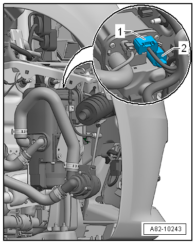
| Should it be difficult to access securing nuts
-2- due to the version of the
headlight, remove headlight
→ Electrical system; Rep. gr.94. |
| – |
Unscrew securing nuts -2- and
remove auxiliary heater from longitudinal member. |
|
|

|
| – |
Open O-type clip -3- and hold
hose -4- so that it points
vertically upwards. |
| – |
Open hose clamp -2- until
coolant emerges from auxiliary heater. |
| – |
Open hose clamp -1- until
coolant emerges from coolant hose -4-. |
| – |
Fit hose -4- and remove hose
clamps, up to Ш 25 mm -3094-. |
| – |
Bleed coolant circuit of auxiliary heater
→ Chapter. |
Note
| If additional air entered cooling system during assembly,
entire coolant circuit must be bled
→ Rep. gr.19. |
| – |
Read event memory and clear entries using vehicle diagnostic
tester in “Guided fault finding” mode. |
| – |
Start auxiliary heater and run it at full load for at least
10 minutes so that fuel line is bled completely and you can
check operation of auxiliary heater. |
| – |
Set dash panel vent to maximum heating power. |
| → Chapter „Assembly overview - auxiliary heater attachments“ |
| Nose insulation; Assembly overview - noise insulation
→ General body repairs, exterior; Rep. gr.66. |
| Wheel housing liner; Removing and installing wheel housing
liner
→ General body repairs, exterior; Rep. gr.66. |
|
|
|
1 -
Bolts
7 Nm
2 -
Heat exchanger
Removing and installing
→ Chapter.
3 -&n ...
Special tools and workshop equipment
required
Torque wrench -V.A.G 1410- (4…20 Nm)
...
Other materials:
Recycling and scrapping end-of-life vehicles
First read and observe the introductory information
and safety warnings Recycling end-of-life vehicles
Volkswagen has already made provision for you to recycle your vehicle in an environmentally
responsible manner. The recycling system operating in many European countries will
take back you ...
Removing and installing seat trim on sill side, standard seat
Note
Removal and installation are described for the left vehicle
side. Follow same instructions for the right side as
appropriate.
Special tools and workshop equipment
required
...
Assembly overview - luggage compartment side trim, estate
Note
The illustration shows the luggage compartment side trim on the
left side. The right-hand side is similar (mirror image of left-hand
side).
1 -
Luggage compartment side trim
Removing and installing
→ Chapter
...
© 2016-2026 Copyright www.vwgolf.org

 Assembly overview - auxiliary heater, interior
 Dismantling and assembling auxiliary heater