Volkswagen Golf Service & Repair Manual: Overview of fitting locations - components not located in passenger
compartment, Golf and Golf GTE, RHD vehicles
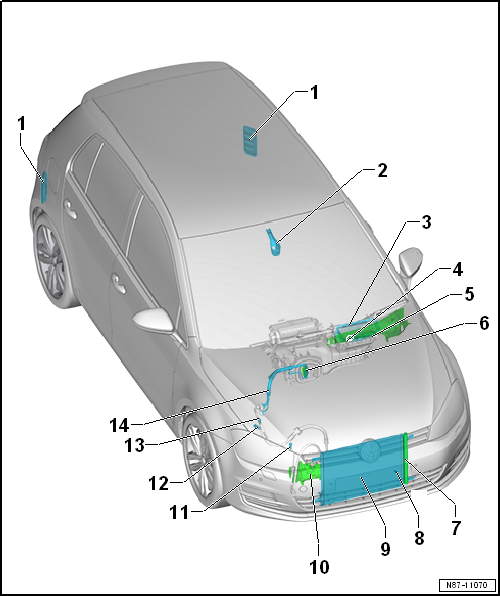
| 1 - |
Exhaust ventilation for passenger compartment |
| Removing and installing
→ Chapter. |
| 2 - |
Humidity sender for air conditioning system -G260- |
| Check via onboard supply control unit -J519-vehicle diagnostic
tester in “Guided fault finding” mode and → Current flow
diagrams, Electrical fault finding and Fitting locations |
| Removing and installing
→ Chapter |
| Removing and installing
→ Chapter |
| 4 - |
Cover for fresh air intake duct |
| Removing and installing
→ Chapter |
| 5 - |
Air quality sensor -G238- |
| Check using vehicle diagnostic tester in “Guided fault finding” mode
and → Current flow
diagrams, Electrical fault finding and Fitting locations |
| Removing and installing
→ Chapter |
| Principles of operation
→ Chapter |
| Only on vehicles with Climatronic. |
| Removing and installing
→ Chapter |
| Specified torques
→ Chapter |
| Removing and installing
→ Chapter |
| Assembly overview
→ Chapter |
| 8 - |
Ambient temperature sensor -G17- |
| Check via onboard supply control unit -J519-vehicle diagnostic
tester in “Guided fault finding” mode and → Current flow
diagrams, Electrical fault finding and Fitting locations |
| Removing and installing
→ Chapter |
| Assembly overview
→ Chapter |
| Removing and installing
→ Chapter |

Note
| Under certain conditions, it is not necessary to renew the receiver
with desiccant bag every time that the refrigerant circuit is opened.
Refer to ELSA under Heating, ventilation, air conditioning system; Air
conditioning system with refrigerant R134a
→ Air conditioning system with refrigerant R134a; Rep. gr.00. |
| 10 - |
Air conditioner compressor |
| Assembly overview
→ Chapter |
| Removing and installing
→ Chapter |
| Removing from and installing on bracket
→ Chapter |
| 11 - |
Evacuating and charging valve, high-pressure side |
| Removing and installing
→ Chapter |
| 12 - |
Pressure sender for refrigerant circuit -G805- |
| Checking: Use vehicle diagnostic tester in “Guided fault finding”
mode and → Current flow
diagrams, Electrical fault finding and Fitting locations |
| Removing and installing
→ Chapter |
| 13 - |
Evacuating and charging valve, low-pressure side |
| Removing and installing
→ Chapter |
| 14 - |
Refrigerant line with internal heat exchanger |
| From condenser and air conditioner compressor |
| Removing and installing
→ Chapter |
1 -
Exhaust ventilation for passenger compartment
Checking
→ Chapter
Removing and installing
→ Chapter.
...
1 -
Exhaust ventilation for passenger compartment
Checking
→ Chapter
Removing and installing
→ Chapter
...
© 2016-2024 Copyright www.vwgolf.org

 Overview of fitting locations - components not located in passenger
compartment, Golf and Golf GTE, LHD vehicles
Overview of fitting locations - components not located in passenger
compartment, Golf and Golf GTE, LHD vehicles Overview of fitting locations - components not located in passenger
compartment, Golf Variant LHD
Overview of fitting locations - components not located in passenger
compartment, Golf Variant LHD