Volkswagen Golf Service & Repair Manual: Removing and installing fuel tank, vehicles with multi-link rear suspension
and fuel tank leakage diagnosis function
| Special tools and workshop equipment
required |
|
|
|
| Torque wrench -V.A.G 1331- |
|
|
|
| Engine and gearbox jack -V.A.G 1383 A- |
|
|
|
| Engine and gearbox jack -VAS 6931- |
|
|
|
| Torque wrench -V.A.G 1332- |
| – |
Observe safety instructions
→ Chapter. |
| – |
Observe rules for cleanliness
→ Chapter. |
| – |
Move front seats to foremost position. |
| – |
Remove rear bench seat
→ General body repairs, interior; Rep. gr.72. |
| – |
Draining fuel tank
→ Chapter |
|
|
|
| – |
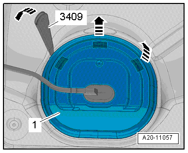
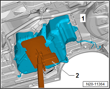
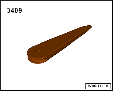
Unclip cover -1- for flange at
retaining tabs -arrows-, using
removal wedge -3409-. |
|
|
|
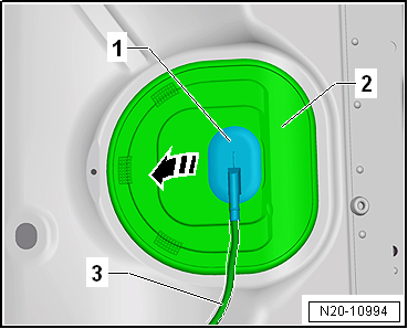
| – |
Unclip sealing grommet -1-
downwards from cover -2-. |
| – |
Push cover -2- back along
wiring harness -3-. |
|
|
|
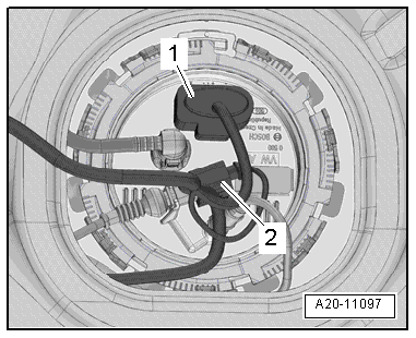
| – |
Release and pull off connector -1-
on sealing flange. |
| – |
If fitted, detach connector -2-
for metering pump -V54- of auxiliary heater on sealing flange
and lay connector aside. |
| – |
Release and pull off connector -2-. |
|
|
|
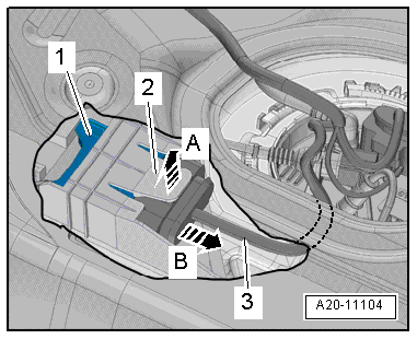
| – |
Press up tab -2- in
-direction of arrow A-; to do so,
reach between floor panel and fuel tank with your finger. |
| – |
At the same time, carefully pull fuel pump control unit
-J538--1- out of mounting
-in direction of arrow B- by
grasping hold of wiring harness -3-. |
| – |
Guide fuel pump control unit -J538- out towards interior
between fuel tank and floor panel. |
|
|
|
| – |
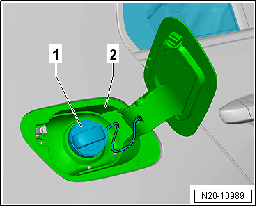
Open tank flap unit -2-. |
| – |
Clean area around fuel filler neck. |
| – |
Unscrew cap -1- for fuel filler
neck. |
 Note Note
| In order to prevent the ingress of dirt, seal the opening of
the fuel filler neck with a clean plug. |
| – |
Remove tank flap unit -2-
→ General body repairs, exterior; Rep. gr.55. |
| – |
Remove rear right wheel
→ Running gear, axles, steering; Rep. gr.44. |
| – |
Remove rear right wheel housing liner
→ General body repairs, exterior; Rep. gr.66. |
| – |
Remove rear underbody cladding
→ General body repairs, exterior; Rep. gr.66. |
|
|
|
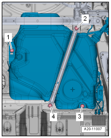
| – |
Unscrew bolts -1- and
-2- for fuel filler neck. |
|
|

|
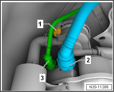
| – |
Pull breather lines -1- and
-2- off activated charcoal filter. |
|
|
|
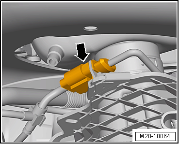
| – |
Release and pull off connector -arrow-. |
|
|
|
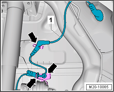
| – |
Unclip wiring harness -1- from
retainers -arrows-. |
| – |
Remove rear section of exhaust system
→ Rep. gr.26. |
|
|
|
| – |
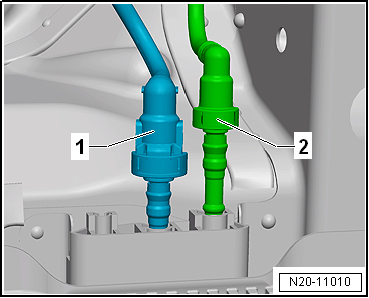
Disconnect fuel line -1- on
underbody. Separate plug-in connectors
→ Chapter. |
The fuel system is pressurised.Risk of injury due to fuel which may
spurt out.Wear eye protection.Wear protective gloves.Release pressure:
place clean cloth around connection and carefully open connection.
| – |
Disconnect breather line -2-.
Separate plug-in connectors
→ Chapter. |
| – |
If rear underbody cladding is fitted, remove it
→ General body repairs, exterior; Rep. gr.66. |
|
|
|
| – |
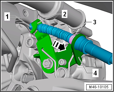
Push lever -2- on brake caliper
in -direction of arrow-, and detach
handbrake cable -1-. |
| – |
Press together locking lugs -3-,
and remove handbrake cable from bracket
-4- on brake caliper. |
|
|
|
| – |
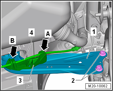
Unclip handbrake cable -4- from
retainer -arrow A-. |
| – |
Pull handbrake cable out of guide
-arrow B- on retainer -3-. |
| – |
Unscrew bolts -2-, and swing
trailing arm -1- downwards. |
|
|
|
| – |
Remove bracket for exhaust system. |
| – |
Unscrew bolt -2- and remove
securing strap. |
|
|
|
| – |
Place engine and gearbox jack under fuel tank
-1- to support it. |
|
|
|
| – |
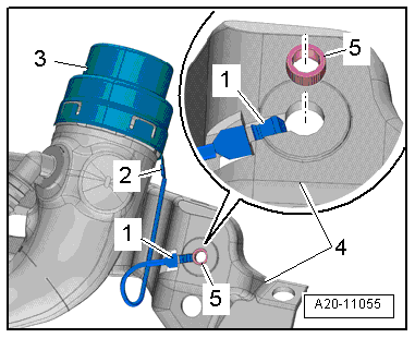
Check whether there are signs of oxidation on the earth wire
of the connectors, remove if necessary. |
| – |
Check installation position of earth connection. |
| Ensure that connector -2- is
seated securely on metal ring -3-. |
| Contact tab -1- must be
attached to fuel tank -4- and
secured with spacer bush -5-. |
| – |
Check contact of metal ring on fuel filler neck by measuring
resistance between ring and bare metal on body using an
ohmmeter. |
| Specification: approx. 0 ohm. |
| If the specification is not attained, there is a risk of
explosion due to electrostatic discharge. |
| – |
Fill fuel tank with at least 5 litres of fuel. |
Risk of explosion of fuel tank caused by fuel pump activation.Risk of
severe injuries and burns.If a new or completely empty fuel tank has
been installed, fill it immediately with at least 5 litres of fuel.
| → Chapter „Assembly overview - fuel tank, vehicles with
multi-link rear suspension“ |
| → General body repairs, interior; Rep. gr.72 |
| → General body repairs, exterior; Rep. gr.55 |
| → General body repairs, exterior; Rep. gr.66 |
| → Running gear, axles, steering; Rep. gr.42 |
|
|
|
1 -
Breather line
To activated charcoal filter
Do not kink
Clipped onto fuel tank
To pull off, press rele ...
Special tools and workshop equipment required
Removal wedge -3409-
Remote control -V.A.G 1348/3A-
Test instrument adapter/DSO (5-pin) -V ...
Other materials:
Introduction
This chapter contains information on the following subjects:
→ Warning lamp
→ Frontal collisions and the laws of physics
→ What happens to vehicle occupants who have not fastened their seat belts
→ Seat belt protection
→ Using seat bel ...
Information on steering
First read and observe the introductory information
and safety warnings The steering should be locked every time you leave the
vehicle to make it more difficult for the vehicle to be stolen.
Electronic steering column lock
Vehicles with Keyless Access: the steering column will be locked if ...
General notes on tyre noise
Tyre noise that can be heard by the human ear is caused by
vibrations which are transmitted by the air from the source of
the sound to our ears.
Of interest here are the noises caused by certain
characteristics and effects while the tyre ...
© 2016-2024 Copyright www.vwgolf.org

 Assembly overview - fuel tank, vehicles with four-wheel drive
 Emptying fuel tank when fuel pump is intact