Volkswagen Golf Service & Repair Manual: Fixing position of subframe, multi-link suspension, front-wheel drive, Golf
GTE
| Special tools and workshop equipment
required |
|
|
|
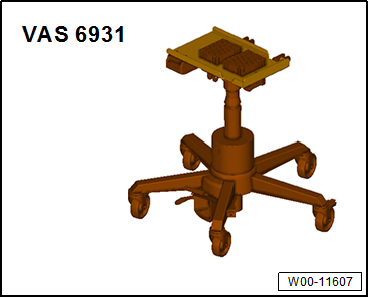
| Engine and gearbox jack -VAS 6931- |
| Installing locating pins -T10096- |
|
|
|
| – |
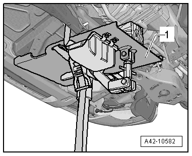
Position engine and gearbox jack -VAS 6931--1-
underneath subframe, and secure with tensioning strap. |
|
|
|
| – |
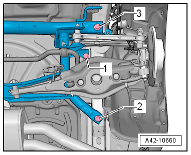
Unscrew bolt -1- on both sides. |
| To fix position of subframe, locating pins -T10096- must be
screwed in successively at positions -2-
and -3- on both sides of vehicle. |
|
|
|
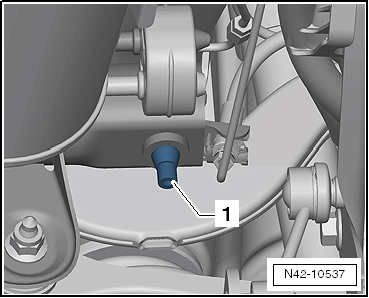
| – |
Remove one of the front bolts of the subframe
-arrow- |
|
|

|
| – |
Screw in locating pins -T10096--1-. |
 Note Note
| The locating pins -T10096- may be tightened only to a
maximum of 20 Nm; otherwise the threads of the locating pins may
be damaged. |
| – |
This procedure must now be carried out for the second front
bolt and the rear bolts of the subframe. |
| The position of the subframe is now fixed. |
|
|
|
Special tools and workshop equipment
required
Locating pins -T10096-
...
Special tools and workshop equipment
required
Locating pins -T10096-
...
Other materials:
Checking steering column for damage
Visual check
–
Check all steering column parts for damage.
Checking function
–
Check that steering column turns smoothly and easily.
–
Check whe ...
Switching TCS or TCS with ESC on and off
Fig. 142 In the centre console: button
for switching the traction control system (TCS) or electronic stability control
(ESC) on and off manually
Fig. 143 In the centre console: button
for switching the traction control system (TCS) on and off manually (vehicles without
ESC)
First read an ...
Measurement location
Note
The vehicle shown in the illustration may differ from the actual
vehicle.
1 -
Volkswagen logo
Laser pointer aligned to centre of Volkswagen logo
2 -
Wheel centre mounting -VAS 6350/1-
...
© 2016-2026 Copyright www.vwgolf.org


 Fixing position of subframe, multi-link suspension, front-wheel drive,
except for e-Golf and Golf GTE
Fixing position of subframe, multi-link suspension, front-wheel drive,
except for e-Golf and Golf GTE Fixing position of subframe, multi-link suspension, four-wheel drive