Volkswagen Golf Service & Repair Manual: Assembly overview - valves
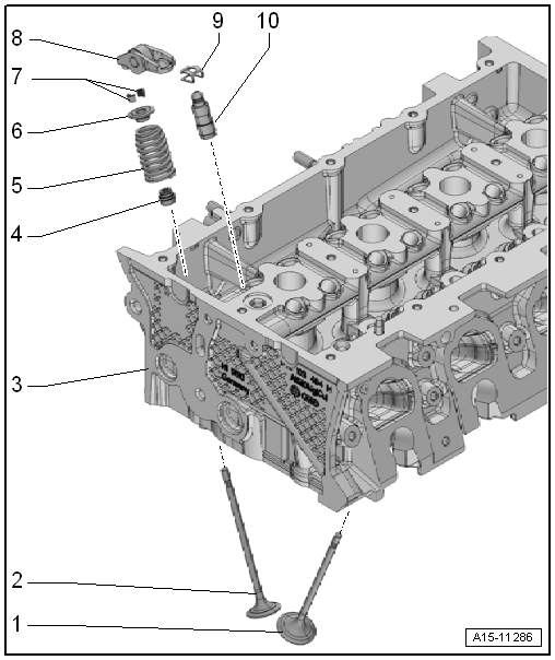
| 1 - | Inlet valve |
| Do not rework. Only lapping in is permitted. |
| Valve dimensions → Chapter |
| Checking valve guides → Chapter. |
| 2 - | Exhaust valve |
| Do not rework. Only lapping in is permitted. |
| Valve dimensions → Chapter |
| Checking valve guides → Chapter. |
| 3 - | Cylinder head |
| 4 - | Valve stem seal |
| Renew → Chapter |
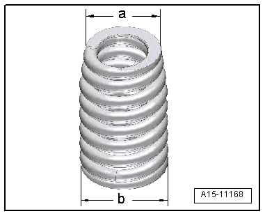
| 5 - | Valve spring |
| Installation position → Fig. |
| 6 - | Valve spring plate |
| 7 - | Valve cotters |
| 8 - | Roller rocker finger |
| Removing and installing → Chapter „Removing and installing camshaft housing“ |
| Mark installation position for re-installation. |
| Check roller bearing for ease of movement. |
| Lubricate contact surfaces before installing. |
| 9 - | Securing clip |
| For hydraulic compensation element. |
| 10 - | Hydraulic compensation element |
| Do not interchange |
| Oil contact surface |
|
|
 Valve gear
...
 Removing and installing camshaft control valve 1 -N205- and exhaust camshaft
control valve 1 -N318-
Removing and installing camshaft control valve 1 -N205- and exhaust camshaft
control valve 1 -N318-
Note
On engines with codes CMBA, CPVA, CXSA, CZCA and CPVB, only
camshaft control valve 1 -N205- is installed.
Removing
...
Other materials:
Assembly overview - backrest release mechanism and entry assistance
1 -
Connecting Bowden cable
Between backrest release mechanism and mounting bracket for backrest
release mechanism
Removing and installing
→ Chapter
2 -
Trim for backrest release mechanism
Removing and installing ...
Removing and installing electronics box (E-box)
Removing
–
With ignition switched off, disconnect earth cable from
battery
→ Chapter.
Diesel engine
–
Remove engine control unit and lay to one side with
...
Removing and installing gas discharge bulb -L13-/-L14-
WARNING
Risk of death due to high voltage! Risk of injury
and environmental pollution!
Observe operation and safety notes for gas discharge
bulbs
→ Chapter.
...
