Volkswagen Golf Service & Repair Manual: Assembly overview - brake servo/brake master cylinder, LHD vehicles
 Note Note
| Only use new brake fluid conforming to VW standard (VW 501 14). |
|
|
|
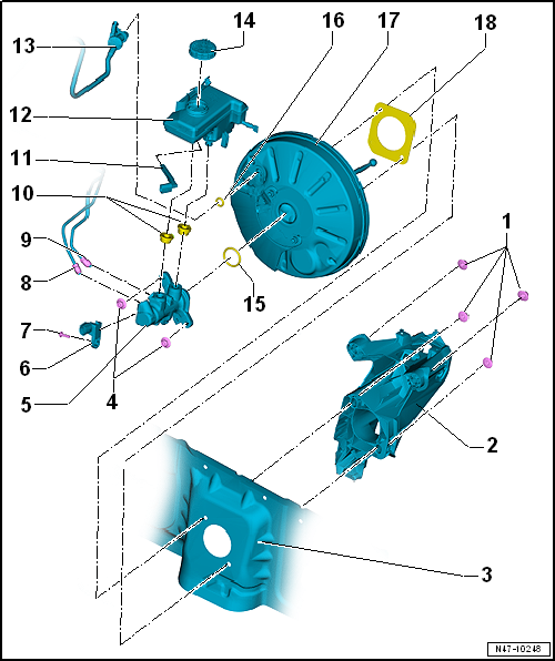
| 1 - |
Self-locking hexagon nut |
| Always renew after removing |
| 2 - |
Pedal cluster with mounting bracket |
| 3 - |
Plenum chamber bulkhead |
| 4 - |
Self-locking hexagon nut |
| Always renew after removing |
| 5 - |
Brake master cylinder |
| Cannot be repaired. If faulty, renew as a complete unit. |
| Removing and installing
→ Chapter |
| 6 - |
Brake light switch -F- |
| Removing and installing
→ Chapter |
| From secondary piston circuit of brake master cylinder to hydraulic
unit. |
| From primary piston circuit of brake master cylinder to hydraulic
unit. |
| Moisten with brake fluid and press into brake fluid reservoir. |
| 11 - |
Brake fluid level warning contact --F34-- |
| 12 - |
Brake fluid reservoir |
| On some vehicles with petrol engines, vacuum sender -G608- is
installed in brake servo
→ Chapter |
| Vacuum hose for brake servo |
| Between brake master cylinder and brake servo |
| – |
With engine switched off, depress brake pedal firmly several times
(to exhaust vacuum in unit). |
| – |
Now step on and hold brake pedal with medium pressure and start
engine. If the brake servo is functioning properly, the brake pedal will
be felt to go down as the servo takes effect. |
| Replace completely in the event of a fault (before doing so, check
brake servo vacuum system)
→ Chapter |
| Removing and installing
→ Chapter |
| Bonded (only when originally assembled at factory) |
| Bonded joint at brake servo and plenum chamber bulkhead does not
have to be renewed |
Note
Only use new brake fluid conforming to VW standard (VW 501 14).
1 -
Cap
...
Other materials:
Introduction
This chapter contains information on the following subjects:
→ Warning lamp
→ Childproof lock
Additional information and warnings:
Vehicle key set
Instruments
Central locking system
Manual opening and closing
WARNING
Any door ...
Removing and installing bulbs for cornering light -L148-/-L149-
Note
Left cornering light bulb -L148- and right cornering light
bulb -L149- are only fitted on gas discharge headlights.
Removal and installation are described for the left side.
Removal and installation on the right ...
Test preparations, wheel alignment with driver assist systems
The following steps are required if one or more driver
assist systems on the vehicle are to be calibrated via the
“Quick-start” procedure (i.e. without first checking and
adjusting the wheel alignment):
Before driving the vehic ...
© 2016-2026 Copyright www.vwgolf.org


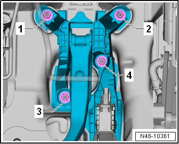

 Assembly overview - brake servo/brake master cylinder, RHD vehicles