Volkswagen Golf Service & Repair Manual: Removing and installing coolant pipes for auxiliary heater
| Special tools and workshop equipment
required |
|
|
|
| Torque wrench -V.A.G 1410- (4…20 Nm) |
|
|
|
| Hose clamps, up to 25 mm -3094- |
|
|
|
| Pliers for spring-type clips -VAS 5024A- |
|
|
|
| – |
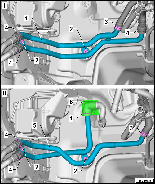
Loosen spring-type clip -3-. |
| – |
If fitted (only on specific vehicles), slide protective
grommet -6- to one side. |
| – |
Unclip coolant hoses -4- and
pull them off coolant pipes -1- and
-5-. |
| – |
Remove coolant pipes -1- and
-5-. |
| – |
Install in reverse order. |
|
|
|
|
Component to be tightened |
Specified torque |
| Collar nut |
8 Nm |
| Nose insulation; Assembly overview - noise insulation
→ General body repairs, exterior; Rep. gr.66. |
|
|
|
The removal and installation procedures for the auxiliary
heater and the circulation pump -V55- described in this Workshop
Manual ensure that only a small quantity of ...
Other materials:
Run-flat tyre system PAX, support ring
Dimensions
Overview of important dimensions:
Codes/designations
Example: 90-500(35) CLI A 1 876107
90 -
Nominal width in millimetr ...
Vibration, causes for vibration
Vibration can have a number of different causes. Vibration
can also be caused by tyre wear. Tyre wear caused by driving is
not always evenly spread across the entire running surface of
the tyre. This causes slight imbalances which affect the smooth
runni ...
Removing and installing tail light bulb -M2-/-M4-
Note
Removal and installation are described for the left side.
Removal and installation on the right side are carried out in
the same way.
Removing
–
Turn light switch to “0” position.
...
© 2016-2026 Copyright www.vwgolf.org

 Note
Note
 Bleeding coolant circuit of auxiliary heater