Volkswagen Golf Service & Repair Manual: Removing and installing bulbs for cornering light -L148-/-L149-
 Note Note
| Left cornering light bulb -L148- and right cornering light
bulb -L149- are only fitted on gas discharge headlights. |
| Removal and installation are described for the left side.
Removal and installation on the right side are carried out in
the same way. |
|
|
|
| – |
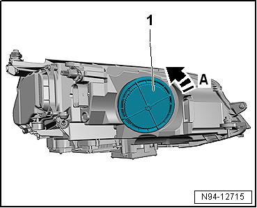
Turn housing cover -1- in
direction of arrow -A- and remove
it from headlight. |
|
|
|
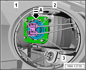
| – |
Press bulb holder -1- down
-arrow A-. |
| – |
Pull bulb holder -1- out of
reflector -2-. |
| – |
Disconnect electrical connector. |
| Install in the reverse order of removal, observing the
following: |
 Caution
| Risk of damage to the headlight. |
| Do not touch the glass part of the bulb with bare
fingers. Fingers leave traces of grease on the glass
bulb, which vaporise when the bulb is switched on and
cause the glass bulb to cloud over. |
| Wear, for example, clean fabric gloves when
inserting bulbs. |
| Make sure the housing cover is correctly seated when
installing. The ingress of water will lead to permanent
damage to the headlight. |
|
| – |
Check headlight setting and adjust headlight if necessary
→ Booklet36.1 |
|
|
 |
Note
Left dip beam screen motor -V294- and right dip beam screen
motor -V295- are only fitted on gas discharge headlights without
cornering light ...
WARNING
Risk of death due to high voltage! Risk of injury
and environmental pollution!
...
© 2016-2026 Copyright www.vwgolf.org

 Removing and installing dip beam screen motor -V294-/-V295
 Removing and installing gas discharge bulb control unit -J343-/-J344-