Volkswagen Golf Service & Repair Manual: Overview of fitting locations - injection system
| Overview of fitting locations - engine compartment |
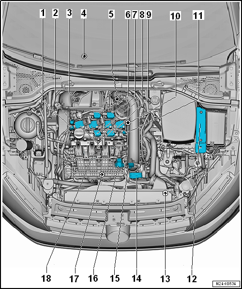
| 1 - |
Inlet camshaft control valve 1 -N205- |
| Removing and installing
→ Chapter |
| 2 - |
Exhaust camshaft control valve 1 -N318- |
| Only installed in vehicles with engine codes CPTA, CHPA, CZEA, CZDA |
| Removing and installing
→ Chapter |
| 3 - |
Lambda probe 1 before catalytic converter -GX10- |
| |
Lambda probe heater -Z19- |
| Removing and installing
→ Chapter |
| 4 - |
Lambda probe 1 after catalytic converter -GX7- |
| |
Lambda probe after catalytic converter -G130- |
| |
Lambda probe heater 1 after catalytic converter -Z29- |
| Removing and installing
→ Chapter |
| 5 - |
Charge air pressure controller -V465- |
| Removing and installing
→ Chapter |
| 6 - |
Exhaust cam actuator for cylinder 2 -N587- |
| Only installed in vehicles with engine codes CPTA, CZEA |
| Removing and installing
→ Chapter |
| 7 - |
Exhaust cam actuator for cylinder 3 -N595- |
| Only installed in vehicles with engine codes CPTA, CZEA |
| Removing and installing
→ Chapter |
| 8 - |
Inlet cam actuator for cylinder 2 -N583- |
| Only installed in vehicles with engine codes CPTA, CZEA |
| Removing and installing
→ Chapter |
| 9 - |
Inlet cam actuator for cylinder 3 -N591- |
| Only installed in vehicles with engine codes CPTA, CZEA |
| Removing and installing
→ Chapter |
| 10 - |
Hall sender 3 -G300- |
| Only installed in vehicles with engine codes CPTA, CHPA, CZEA, CZDA |
| Removing and installing
→ Chapter |
| Removing and installing
→ Chapter |
| 12 - |
Engine control unit -J623- |
| Removing and installing
→ Chapter |
| 13 - |
Radiator outlet coolant temperature sender -G83- |
| Removing and installing
→ Chapter |
| 14 - |
Throttle valve module -GX3- |
| |
Throttle valve module -J338- |
| |
Throttle valve drive for electronic power control -G186- |
| |
Throttle valve drive angle sender 1 for electronic power control
-G187- |
| |
Throttle valve drive angle sender 2 for electronic power control
-G188- |
| Removing and installing
→ Chapter |
| 15 - |
Charge air pressure sender -GX26- |
| |
Charge air pressure sender -G31- |
| |
Intake air temperature sender -G42- |
| Removing and installing
→ Chapter |
| 16 - |
Intake manifold sender -GX9- |
| |
Intake air temperature sensor 2 -G299- |
| |
Intake manifold pressure sender -G71- |
| Removing and installing
→ Chapter |
| 17 - |
Charge air cooling pump -V188- |
| Removing and installing
→ Chapter |
| 18 - |
Ignition coils with output stages |
| Ignition coil 1 with output stage -N70- |
| Ignition coil 2 with output stage -N127- |
| Ignition coil 3 with output stage -N291- |
| Ignition coil 4 with output stage -N292- |
| Removing and installing
→ Chapter |
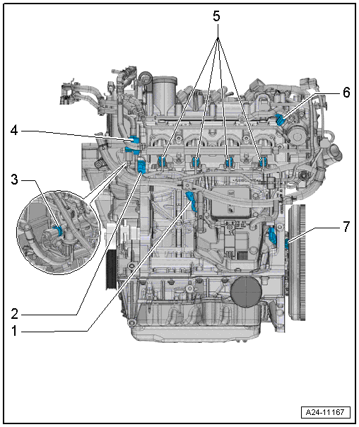
| Overview of fitting locations – engine, intake side |
| Assembly overview
→ Chapter |
| 2 - |
Oil pressure switch for reduced oil pressure -F378- |
| Assembly overview
→ Chapter |
| 3 - |
Fuel pressure sender -G247- |
| Assembly overview
→ Chapter |
| 4 - |
Activated charcoal filter solenoid valve 1 -N80- |
| Injector, cylinder 1 -N30- |
| Injector, cylinder 2 -N31- |
| Injector, cylinder 3 -N32- |
| Injector, cylinder 4 -N33- |
| Assembly overview
→ Chapter |
| 6 - |
Fuel pressure regulating valve -N276- |
| Assembly overview
→ Chapter |
| 7 - |
Engine speed sender -G28- |
| Assembly overview
→ Chapter |
| Overview of fitting locations – engine, exhaust side |
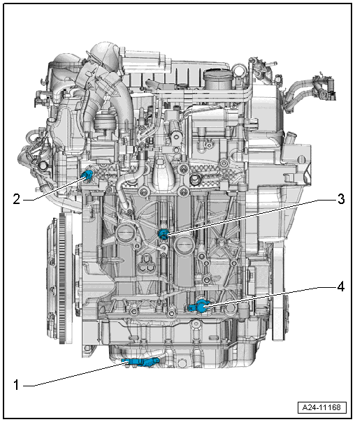
| 1 - |
Oil level and oil temperature sender -G266- |
| Removing and installing
→ Chapter |
| 2 - |
Coolant temperature sender -G62- |
| Removing and installing
→ Chapter |
| 3 - |
Oil pressure switch -F1- |
| Removing and installing
→ Chapter |
| 4 - |
Oil pressure control valve -N428- |
| Removing and installing
→ Chapter |
The fuel system is under high pressure.Risk of
injury due to fuel which may spurt out.Release high pressure.
Special tools and workshop equipment
required
...
Other materials:
Air conditioner compressor without magnetic clutch
The air conditioner compressor is driven by a V-belt from
the engine.
A shear link is incorporated in the air conditioner
compressor V-belt pulley. In the event of stiffness in the air
conditioner compressor, it shears off and protects t ...
Removing and installing rear fog light bulb -L46-/-L47-
Note
Removal and installation are described for the left side.
Removal and installation on the right side are carried out in
the same way.
Removing
–
Turn light switch to “0” position.
...
O-ring
Use only O-rings that are resistant to refrigerant R134a and
related refrigerant oils. O-rings are no longer colour-coded.
Coloured and black O-rings are used.
Check that the O-rings used have the correct internal
diameters.
...
© 2016-2026 Copyright www.vwgolf.org

 Injection system
 Releasing high pressure in fuel system