
Volkswagen Golf Owners Manual: Displays, warning and indicator lamps
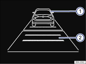
Fig. 166 In the instrument cluster display: ACC deactivated temporarily; vehicle detected ahead, time interval set
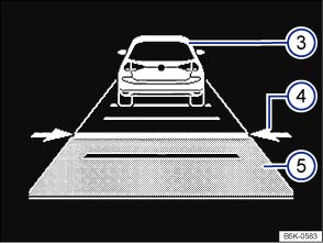
Fig. 167 In the instrument cluster display: ACC active: vehicle detected ahead, time interval is being set
 First read and observe the introductory information
and safety warnings
Displays
Display fields or :
 Vehicle ahead when ACC is inactive.
 Selected distance range when ACC is
inactive.
 Vehicle detected ahead. ACC is active.
 Setting the time interval to the vehicle
in front while travelling at stored speed.
 Time interval to the vehicle in front
while travelling at stored speed has been set.
Warning and indicator lamps
| Lit up | Possible cause | Solution |
|---|---|---|
 |
ACC speed reduction between the vehicle ahead is insufficient. | Brake! Depress the brake pedal. The system tells the driver to take control. |
  |
ACC currently not available.a) | Switch off the engine and restart it while stationary. Inspect the radar sensor (for dirt, ice etc.). Go to a qualified workshop immediately and have the system checked if it is constantly unavailable. |
 |
ACC is active. No vehicle has been detected ahead. The set speed is kept constant. | – |
 |
When displayed in white: ACC active. Vehicle detected ahead. ACC regulates the speed and the distance from the vehicle ahead. | – |
| When displayed in grey: ACC not active. System switched on, does not regulate. | ||
 |
ACC is active. | – |
Several warning and indicator lamps will light up briefly as a functional check when the ignition is switched on. They will switch off after a few seconds.

 WARNING
- Never ignore any illuminated warning lamps or text messages.

 NOTICE

a) Displayed in colour on an instrument cluster with colour display.
 Introduction
This chapter contains information on the following subjects:
→ Displays, warning and indicator lamps
→ Radar sensor
→ Operating Adaptive Cruise Control (ACC)
...
 Radar sensor
Fig. 168 In the front bumper: radar sensor
First read and observe the introductory information
and safety warnings A radar sensor is fitted to the front bumper to monitor
the traffic situatio ...
Other materials:
Assembly overview - seat pan
Seat pan, standard seat, seat of type "ergo Aktiv"
Note
The illustration shows the driver seat pan. The front
passenger seat pan is similar (mirror image of driver seat pan).
The illustration shows the seat p ...
Overview of fitting locations – fuse box, battery (vehicles with
high-voltage system)
1 -
Battery -A-
Removing and installing
→ Chapter
Disconnecting and connecting
→ Chapter
2 -
Bolt
3.5 Nm
3 -
Nut
7.5 Nm
...
Removing and installing window channel
Note
The removal and installation sequence is only for the
left window channel. Removal and installation of the right
window channel are similar.
Do not bend window channe ...
