Volkswagen Golf Owners Manual: Changing bulbs in the halogen headlights
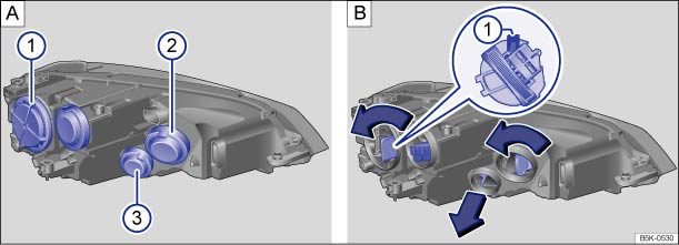
Fig. 234 In the engine compartment: covers on the left front headlight ① dipped beam, ② main beam, side lights and daytime running lights, ③ turn signal
 First read and observe the introductory information
and safety warnings
First read and observe the introductory information
and safety warningsThe front headlight does not need to be removed when changing bulbs.
| The actions should only be carried out in the specified order: | ||||
|---|---|---|---|---|
| ① | ② | ③ | ||
| Dipped beam headlights | Side light (small bulb holder) | Main beam/daytime running lights or daytime headlights | Front turn signal | |
| 1. | Observe and follow the instructions on the checklist. | |||
| 2. |
Open the bonnet  . . |
|||
| 3. |
Remove the rubber cover on the rear of the headlight. Depending on the model, a hard plastic cover may also be fitted. Turn the cover anticlockwise and remove it. |
|||
| 4. | Turn the bulb holder anticlockwise as far as it will go and carefully pull it out to the rear along with the bulb. | Pull the bulb holder and the bulb out to the rear, and carefully guide them sideways out of the opening. | ||
| 5. | Replace the defective bulb with a new bulb of the same type. | |||
| 6. | With the retaining lug facing upwards B ①, insert the bulb holder into the headlight and turn it clockwise as far as it will go. | Carefully insert the bulb holder into the headlight and push it towards the front until it clicks into place. | ||
| 7. | Attach the rubber cover or hard plastic cover and turn it clockwise as far as it will go. | |||

The illustrations show the left-hand headlight from the rear. The right-hand headlight is a mirror image of the one shown.
There are various types of front headlight, so the position and design of covers, bulbs and bulb holders may vary from those shown in the illustrations.
It is not possible to change the LEDs of a daytime running light with LED technology. Proceed to a qualified workshop.
 Checklist
Always carry out the following actions for changing a bulb in the
given order :
Park the vehicle on a firm and level
surface at a safe distance from the flow of traffic.
Switch on the ...
 Changing bulbs in xenon headlights
Fig. 235 In the engine compartment: ① cover
in left-hand xenon headlight, ② cornering light, ③ turn signal, ④ side light and
daytime running light
First read and observe the introductory ...
Other materials:
Without needing to purge refrigerant circuit of contaminants (e.g. damage in
an accident); no refrigerant has escaped and no moisture or dirt has entered
refrigerant circuit
Drain refrigerant circuit.
–
Renew restrictor. Depending on vehicle
–
Remove receiver or reservoir.
–
Clean any dirt out of receiver or reservoir.
...
Changing headlights over from driving on left to driving on right (gas
discharge headlights for cornering light and LED daytime running light)
If a right-hand drive vehicle is driven in a left-hand drive
country, or vice versa, the headlights must be converted. This
is necessary in order to avoid dazzling oncoming traffic with
the asymmetric low beam headlights.
Note
...
Overview of fitting locations - seat belts and anchorage points, estate
1 -
Front belt buckles
Assembly overview
→ Chapter
Removing and installing
→ Chapter
2 -
Front belt end anchor
Assembly overview
→ Chapter
Removing and installing
→ Chapte ...
