Volkswagen Golf Owners Manual: Attaching the mounts and roof carrier
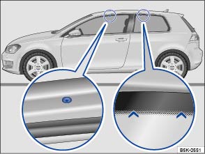
Fig. 105 Attachment points for the mounts and roof carrier on 2-door vehicles

Fig. 106 Attachment points for the mounts and roof carrier on 4-door vehicles
 First read and observe the introductory information
and safety warnings
First read and observe the introductory information
and safety warnings The mounts are the basis of a complete roof carrier system. Special fixtures must then be added to transport luggage, bicycles, skis, surfboards or boats safely on the roof. Suitable accessories are available from your Volkswagen dealership.
Securing the mounts and roof carrier on 2-door vehicles
You must observe the fitting instructions that were delivered with the roof carrier.
The attaching holes at the front are on the underside of the roof side members. They are sealed with plastic screws (left close-up). The holes are only visible when the door is open. The markings for attaching at the rear are at the top on the rear side windows (right close-up).
The roof carrier must only be attached at the holes and markings shown in the illustration.
Securing the mounts and roof carrier on 4-door vehicles
You must observe the fitting instructions that were delivered with the roof carrier.
The attaching holes at the front are located on the underside of the roof side members. They are sealed with plastic screws that must be removed before installation (left close-up). The markings for attaching at the rear are on the underside of the roof side members (right close-up).
The holes and markings are only visible when the door is open.
The roof carrier must only be attached at the markings shown in the illustration.

 WARNING
- Always observe the manufacturer's instructions.
- Only use mounts and roof carriers when they are undamaged and fitted correctly.
- The roof carrier must only be attached at the holes and markings shown in the illustration or .
- Fit mounts and roof carriers correctly.
- Check the bolts and anchorage points before starting your journey and adjust as necessary after driving a short distance. During a long trip, check all bolts and fasteners at each stop.
- Special fixtures for items such as bicycles, skis, surfboards, etc. should always be properly installed.
- Do not carry out any alterations or repairs to the mounts and roof carrier.

Read and observe the instructions provided for the fitted roof carrier system and carry them in the vehicle at all times.
 Introduction
This chapter contains information on the following subjects:
→ Attaching the mounts and roof carrier
→ Loading the roof carrier
The roof of the vehicle has been designed for ...
 Loading the roof carrier
First read and observe the introductory information
and safety warnings Loads can only be attached securely when the roof carrier
system is fitted correctly .
Maximum permissible roof load ...
Other materials:
Removing and installing knee airbag with driver side knee airbag igniter
-N295-
Removing
WARNING
Observe safety instructions for
pyrotechnic components → Chapter.
...
Removing and installing control unit for fuel tank leak detection -J909-
Removing
Fitting location
→ Item:
–
Release and pull off connector -arrow-
on control unit for fuel tank leak detection -J909--1-.
...
First aid kit, warning triangle and fire extinguisher
Fig. 208 In the tailgate: holder for the
warning triangle
First read and observe the introductory information
and safety warningsHigh-visibility waistcoat
In some vehicles there is a stowage compartment for a high-visibility waistcoat
in the driver door .
Warning triangle
With the tail ...
